
![]()
A research team at Yokohama National University, Japan, has prototyped small-sized silicon-photonics chip that can be used for non-mechanical lidar beam steering and scanning. [Image: Yokohama National University]
In principle, lidar systems can act as 3D sensors for applications ranging from autonomous vehicles and robots to security and mapping. In practice, though, the complex moving parts in many lidar systems can make them bulky, unreliable and expensive, limiting their utility.
Researchers at Yokohama National University, Japan, have now used a photonic crystal that supports a “slow light” mode to develop a small silicon-photonics chip that allows for non-mechanical 2D beam steering (Optica, doi: 10.1364/OPTICA.381484). While the proof-of-principle device has further to go in achieving resolution comparable to mechanically steered systems, the team sees several possible ways to surmount that hurdle—putting another candidate in the race for practical solid-state lidar.
Ditching moving parts
Lidar maps the distance to objects using pulsed laser light. By measuring the time-of-flight of photons that bounce off of objects and return to the sensor, lidar systems can create a 3D representation of the surrounding area. A typical lidar system comprises a laser, a photodetector and an optical beam-steering device. The latter has traditionally employed a mechanical system, such as rotary mirrors, to direct light—a design that can add bulk, cost and instability to lidar systems, as well as limiting speed.
For these reasons, there’s a lot of interest in non-mechanical or solid-state devices. One non-mechanical option that has gained traction is optical phased arrays (OPAs)—ranks of tiny optical antennas manufactured to steer light in different direction. But this route has its own set of hurdles. As very large numbers of optical antennas begin to be integrated into a single chip, controlling and calibrating the OPAs becomes complex, according to the Yokohama research team, and there’s a trade-off between the steering range, resolution and efficiency.
Slowing things down
Instead, the Yokohama team, led by OSA member Toshihiko Baba, employed a very different approach—one that used not OPAs, but a set of silicon-photonics lattice-shifted photonic crystal waveguides (LSPCWs). It turns out that such a waveguide, when the holes in the photonic crystal show a certain kind of double periodicity, supports a slow-light mode as a laser pulse interacts with the waveguide. The slow light is then emitted into free space, where it forms a beam that fans out in the direction orthogonal to the waveguide direction.
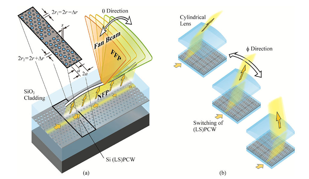
The new beam-steering chip builds on earlier work, in which the Yokohama team used a photonic-crystal architecture that supports a slow-light mode, which can be steered in both the propagation direction (left), by varying the wavelength, and orthogonal to the propagation direction (right), via a convex lens. [Image: H. Abe et al., Opt. Express, doi: 10.1364/OE.26.009389 (2018)] [Enlarge image]
Because the slow-light has a particularly high angular dispersion—that is, the propagation direction varies with wavelength—it can be steered in the direction parallel the waveguide by sweeping the laser beam through different wavelengths. And arranging multiple waveguides side by side, with a convex lens on top, allows the fan-shaped beam to be converted into a point beam, and to be steered in the direction orthogonal to the waveguide as well.
The Yokohama team prototyped just such a 2D beam-steering device in a 2018 paper. But the device had, according to the researchers, “some crucial problems.” Among those were a lot of internal-reflection loss and light loss at the lens, a need for manual lens adjustments, and a restricted steering range.
A better design
In the just-published new work, Baba’s team has overcome those problems. To resolve the light-loss problems, the researchers added a shallow-etched grating (10 nm deep and 200 nm wide) to the silicon LSPCW, to improve the upper emission intensity. They also designed a bespoke prism lens for the setup that converts the steering angle in the desired direction. The lens thickness and curvature maintain the collimation condition for the steered beam across the entire steering range, which the team has doubled by switching the direction of the light incidence on the LSPCW.
By launching light on individual LSPCWs in an 32-LSPCW array, and converting the fan beam into a spot beam with the prism lens, the Yokohama team was able to achieve non-mechanical beam steering using a chip only 5.5×4 mm2 n size.
Beam steering and flexible scanning
The team tested both 1D and 2D beam steering with its device. Using their prism lens, the researchers steered the beam continuously in the range of 40° × 4.4° without adjusting the lens position. They calculated that they obtained 4,256 resolution points in the 2D-steering experiment. However, the researchers expect that with a few adjustments—such as extending the aperture length, fixing fabrication errors in the prism lens and increasing the number of LSPCWs—the device could obtain more than 300,000 resolution points.
The team also demonstrated flexible scans, such as spiral patterns and figure eights, that are difficult to obtain using mechanical systems. This extends the device’s application fields to include optical beam tracking, according to the researchers, where their device—which, they say, can be scaled up without increasing control complexity—could have an advantage over OPAs.
Basing a solid-state 2D beam-steering device on an LSPCW, according to the team, is “the key to realizing a Si photonics non-mechanical lidar system.” The researchers believe that, with some improvements to the prism lens and chip, the device could eventually be used for solid-state lidar as well as security applications and free-space communications.