
 Amsterdam’s “Rainbow Station” project, by artist Daan Roosegaarde. The optical design and implementation were led by Frans Snik and Michiel Rodenhuis of Leiden University, using custom geometric-phase holograms from ImagineOptix Co. [© Studio Roosegaarde]
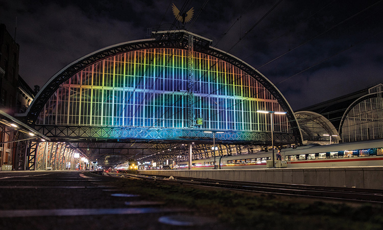
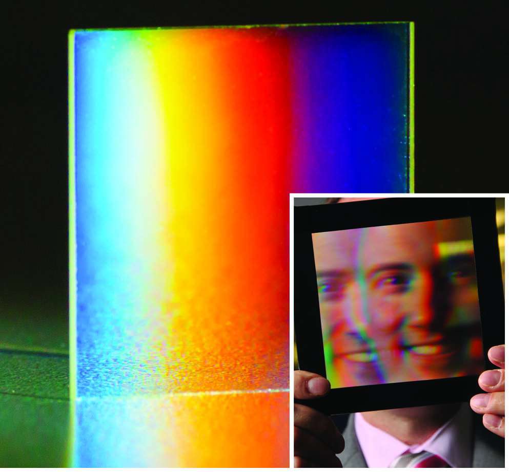
During the International Year of Light (IYL) in 2015, visitors to the historic Central train station of Amsterdam, Netherlands, in the hour after sunset could witness a unique site: the station’s platform-spanning arch, lit by a curved rainbow (opening spread). The “Rainbow Station” project was the brainchild of the Dutch artist Daan Roosegaarde. And the result—a carefully sculpted, arched, richly colored dispersion profile, with minimal leakage of the projected light—was the product of an array of thin optical elements that adjusted the light using a relatively little-known effect called geometric phase.
Until recently, elements taking advantage of this phenomenon—geometric-phase holograms—have been plagued by shortcomings in efficiency, light leakage, and spectral range that have limited their practical use. But improved fabrication technologies are surmounting this hurdle. The result could be a new generation of ultra-thin, versatile gratings, lenses and other optical elements that are already finding use in exoplanet studies, and that could extend to a range of other applications.
A geometric-phase shift arises as a kind of “memory” of the evolution of a lightwave through an anisotropic parameter space.
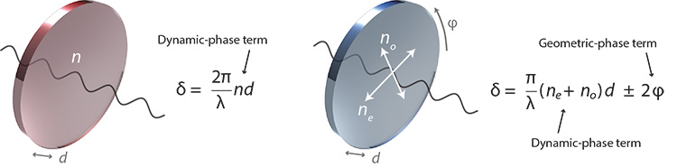 Dynamic and geometric phase: (Left) Dynamic phase relies on variations in optical-element thickness (d) and average refractive index (n), which together affect propagation time through an isotropic plate. (Right) Geometric phase arises from the anisotropy of the plate or surface. In the example of a homogeneous birefringent plate with ordinary and extra-ordinary refractive indices (no) and (ne) and an optic axis orientation (φ), the magnitude of the geometric-phase shift is proportional to twice the orientation angle.
What is geometric phase?
Commonly, a wavefront is controlled by adjusting optical path length (OPL), defined for an isotropic plate as the product of the wave’s speed (dependent on the material’s refractive index) and its physical propagation distance through the medium. An example is the spatially varying OPL caused by a lens’ curved surface. The phase shift that results from such OPL variations is sometimes called a dynamic-phase shift, as these parameters directly affect the wave’s propagation time through a medium.
A geometric-phase shift, by contrast, arises as a kind of “memory” of the evolution of a lightwave through an anisotropic parameter space. Notably, this phase shift depends only on the geometry of the pathway through the anisotropy transforming the lightwave. The most important sources of such transformations are molecular anisotropy and nanostructures causing anisotropic scattering, in which the phase shift of the transmitted or reflected lightwave is directly proportional to the orientation of an effective optic axis, the shape of anisotropic scattering particles, or both. Because this differs remarkably from traditional refraction, it is sometimes referred to as anomalous refraction or reflection.
 GPHs: The efficiency secret
How can a geometric-phase hologram (GPH) achieve 100 percent efficiency in a single useful wave, without multiple higher-order wavefronts? The key is a continuous, effectively unbounded phase shift.
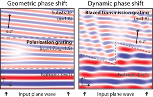
To understand the difference, consider a simple case—a linear phase shift, δ(x) = 2πx/Λ, designed to deflect the incident light by 6.2 degrees into a substrate with refractive index n = 1.6—as accomplished by geometric versus dynamic phase.
For the GPH case, a birefringent polarization grating, the input wave propagates smoothly through the polarization grating layer, because the phase shift experienced by the wave is everywhere continuous. The primary wave exits into the substrate, with a planar wavefront and roughly 100 percent efficiency—the percentage of power in the conjugate wave, leakage wave, and any other potential diffraction orders approaches zero.
For the dynamic-phase embodiment to achieve the same optical goal—a blazed diffraction grating or Fresnel prism—the input wave refracts nicely along most of the inclined interface, but the sharp phase reset in the center causes all manner of scattering. The net efficiency into the primary wave (m = +1) is 81 percent. Although the conjugate (m = –1) and leakage (m = 0) waves each has less than 1 percent efficiency, there are many transmitted higher orders (m ≥ 2) with a total of about 14 percent efficiency, with another 4 percent of efficiency spent in the reflected waves.
In sum, the phase reset in dynamic-phase elements results in unwanted diffracted light, reducing efficiency and introducing artifacts. The lack of such discontinuities in GPHs allows them to embody high-fidelity, continuous phase shifts with high conversion efficiency.
Above: (Left) Finite-difference, time-domain simulation of a GPH across one period (Λ = 6 µm), with 2.5 µm thickness, an anti-reflection layer on the input surface and a 1 µm wavelength, circularly polarized input lightwave. (Right) Analogous simulation of the dynamic-phase element with the same period and wavelength, but with 1.8 µm thickness and linearly polarized input wave. [Michael J. Escuti]
Geometric phase has three particularly remarkable and useful features. First, the geometric-phase-shift magnitude, δ, is solely related to geometrical parameters of the medium creating it. In some implementations, δ is proportional to twice the orientation angle of the local optic axis, ϕ; in others, it depends on both the shape and orientation of an anisotropic scattering particle. Either way, any desired spatially varying phase shift can in principle be embodied in an inhomogeneous anisotropy map. This creates the possibility, as discussed below, of extremely thin optical elements; furthermore, the geometric-phase shift is wavelength independent, notably unlike a dynamic-phase shift (see diagrams).
Second, there is no physical difference between phase shifts of 0 and 2πp, for any integer p, because the embodiment is in orientation, shape, or both. Hence, a relative geometric-phase shift can be both continuously smooth and unbounded, for example, not restricted to 2π (see sidebar). Third, the geometric-phase shift has a sign corresponding to each of two orthogonal polarizations—that is, δ = ±2ϕ, assuming we neglect a dynamic-phase contribution that is constant.
From geometric phase to GPHs
Geometric phase was first described in terms of interference theory by S. Pancharatnam in 1956, and subsequently expanded upon in quantum-mechanical terms by Michael V. Berry in 1984—indeed, it is often referred to as Pancharatnam–Berry phase. Since then, as the optical community has increasingly taken an interest in the phenomenon, researchers have given numerous names to inhomogeneous geometric-phase elements: certain metasurface, polarization or vector holograms; polarization kinoforms; anisotropic aperture antennas; cycloidal diffractive waveplates; and space-variant Pancharatnam–Berry phase optical elements, among others. All operate based on geometric phase, however, and are bound by the same principles. Hence, we refer to all of these elements by a common name: geometric-phase holograms (GPHs).
We define GPHs as those inhomogeneous optical elements that impose a purely geometric-phase shift, and in which isotropic absorption and dynamic phase are constant. Such elements output at most three distinct waves—a primary (“+”) wave, a conjugate (“–”) wave, and a leakage (“0”) wave (see diagrams)—each of which experiences a different geometric-phase shift (or, in the case of the leakage wave, no phase shift). Regardless of the input wave polarization, the primary and conjugate waves have fixed (usually circular), mutually orthogonal polarizations, while the leakage wave retains the input polarization.
Depending on the GPH’s physical characteristics and the input light’s polarization, different relative fractions of input power will couple to the three possible output waves, quantified as the respective conversion efficiencies η+, η–, and η0. Three surprising characteristics of this coupling hint at some powerful advantages of GPHs.
Potentially high efficiency. The theoretical conversion efficiencies follow the relation (1 – A) = (η+ + η– + η0), where A is the net absorbance of the geometric-phase layer, averaged over all phase values from 0 to 2π—with the power lost to absorption proportionally lost from all three output waves. This means that if the net absorbance and leakage efficiency are low, then the maximum efficiency of the primary wave, the conjugate wave, or both may approach 100 percent.
Selectable phase shift. The primary and conjugate efficiencies in most implementations follow the relation η± = (1 – A – η0)(1 ∓ S′3)/2, where S′3 is a normalized Stokes parameter of the input light. Thus, when the input is circularly polarized, only one of the primary or conjugate waves may have power coupled into it, and the orthogonal polarization couples into the other wave. Consequently, the + and – geometric-phase shifts in GPHs may be selected simply by adjusting the input polarization—which, in a given element such as a GP lens, can bring a two-for-one benefit not seen in conventional holograms.
From achromatic to chromatic. The spectral behavior is largely independent of the phase profile, and is determined almost entirely by the properties of the materials or structures creating the anisotropy. Thus the efficiency spectra may range from very achromatic to highly chromatic.
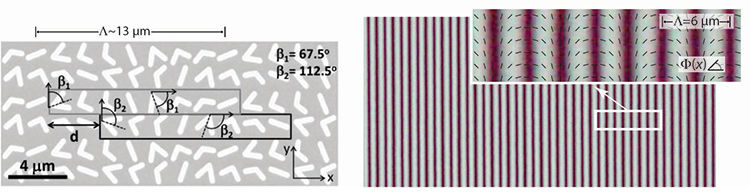 Two ways to make a GPH: (Left) Plasmonic metasurfaces can control the geometric phase through their shape and orientation, and GPHs may be embodied as dense arrays of anisotropic scatterers such as these [Yu et al., IEEE J. of Select. Top. Quant. Electr. 19, 4700423 (2013)]. (Right) Photo-aligned liquid crystals can embody the geometric phase proportional to the local optic axis orientation (little rods). This polarizing optical micrograph of a polarization grating (GP Prism) was taken between crossed polarizers [Michael J. Escuti and Jihwan Kim].
Creating GPHs
Control of geometric phase offers the prospect of versatile, physically thin gratings, lenses and other elements with arbitrary phase profiles. But until recently, owing to inadequate fabrication techniques, pure geometric-phase elements have tended to have low efficiency, high losses (manifest in phenomena such as absorption, haze and parasitic reflections), small clear aperture, spurious leakages, or operating wavelengths outside the visible or near-infrared. Advances in fabrication techniques reported in just the past few years, however, are overcoming these limitations, and resulting in an intriguing array of new optical elements.
Fundamentally, fabricating GPHs involves a twofold challenge: (1) patterning a spatially varying map of (2) something that creates a geometric-phase shift. As long as the molecules or nanostructures are small compared with the wavelength of light, a thin film or surface can support a smoothly varying phase shift. Two leading approaches have emerged to meet that challenge (see micrographs).
Metasurfaces. In one approach, V- or rod-shaped nanoparticles, precisely shaped and oriented into arrays of plasmonic anisotropic scatterers, create a metasurface. Each scattering particle acts as a resonant optical oscillator—a tiny antenna—that absorbs and radiates incident light. The physical and material construction allows a controllable, sharp phase jump between the incident and scattered lightwaves. When closely packed, arrays of scatterers can modify the amplitude, phase, and polarization of incident light in nearly any spatially varying profile, an immensely general and flexible capability. However, several designs have been optimized for a phase-only shift spanning 0 to 2π.
 Geometric-phase prisms
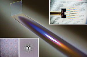
Geometric-phase prisms, or polarization gratings (PGs), are among the oldest and most deeply studied of GPHs. These elements impose the simplest kind of inhomogeneous phase profile: a linear profile, such as the kind of phase change created by a refractive prism. The PGs we study have an ideal linear orientation map, Φ(x) = πx/Λ, where Λ is the period.
These elements act essentially as diffraction gratings, in which the classical grating equation applies—sin θm = mλ/Λ + sin θin—and the primary, conjugate and leakage waves correspond to the diffraction orders m = +1, –1 and zero. When formed with photo-aligned liquid crystals, common experimental efficiencies (η+ + η–) approximate 100 percent. Our research group and others have studied grating periods as low as a few µm and as high as several mm; and sizes of more than 10,000 mm2 are now being made. 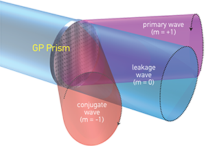 [Michael J. Escuti and Phil Saunders]
Metasurface fabrication methods depend on standard photolithography and materials, albeit at nanoscale resolutions. Nanostructures are usually 50 to 200 nm thick and have lateral dimensions of about a micron or less. Most work thus far has been in the mid-infrared (5 to 12 µm), with some studies within the red to near-infrared (0.6 to 1.1 µm). The efficiency of plasmonic metasurfaces is limited by plasmonic absorption, the antenna scattering amplitude itself and the density of the array. The highest measured peak efficiencies reported thus far have been η++ η–≤ 20 percent in the transmission mode and η++ η–≈ 80 percent in the reflection mode; those values will likely increase in the near future. Bandwidths are generally broad, but depend strongly on the definition being used.
Liquid crystals. An alternative approach, reported on by our lab last year, leverages a common technology in the flat-panel display industry: liquid crystals, which are photo-aligned to precisely orient the average direction of anisotropic molecules. In linearly birefringent materials such as these, the geometric-phase shift arises as a consequence of the polarization evolution as the lightwave propagates.
To pattern the liquid crystal layer, a photo-alignment layer is applied onto the substrate, which records the orientation of a linearly polarized UV recording light and subsequently transfers the orientation to the liquid crystal layer. The principal techniques for creating the UV light pattern are polarized interference lithography and direct-write laser scanning. Total active layer thickness is usually 1 to 10 µm, depending on the operational wavelengths. Photo-aligned liquid crystals are especially well suited for GPHs because they offer large optical anisotropy, with roughly no absorption through at least the wavelength range from 400 to 5,000 nm (except at absorption resonances around 3,000 nm); moreover, the materials used are well understood, highly stable and commercially available.
The liquid crystal technique has achieved GPHs supporting a variety of bandwidths, from visible to infrared, enabled by structuring the liquid crystal in the out-of-plane dimension. Several designs show η++ η–≥ 95 percent efficiency across 425 to 725 nm, 400 to 900 nm and 2,000 to 5,000 nm in both simulation and experiment. Efficiencies in liquid crystal based GPHs are limited by the precision of processes used to form the liquid crystal layer thicknesses (and in many cases chiral twist), as well as potential residual haze from the liquid crystal layer.
 Geometric-phase lenses
Geometric-phase lenses can also be realized. These GPHs can be designed without spherical aberration—for example, when Φ(x,y) = (π/λ0)((x2 + y2+ ƒ2)½ – ƒ), where λ0 is the nominal wavelength and ƒ0 is the corresponding nominal focal length. A normally incident plane wave with wavelength λ0and one circular handedness focuses at a spot z = +ƒ0, while the orthogonal handedness has an apparent focal length of z = –ƒ0.
GP lenses can be arranged as an individual lens or a microlens array, and can be configured as either transmissive or reflective. They offer a compelling route to small F-number lenses: several groups have demonstrated as low as around F/2 for red light, with intense work under way to reduce this to F/1 and beyond for visible and infrared wavelengths. We have realized nearly 100 percent experimental efficiencies in GP lenses for the whole visible spectrum.
GP lenses can also be made very thin—their active layer commonly is a few µm thick or thinner. Thus, even with substrates, their total thickness can be as low as approximately 0.2 mm, regardless of clear aperture size or F-number. Since the minimum thickness is primarily restricted by the availability of thin, free-standing substrates, GP lenses offer a physically compelling option for integration into many optical systems, often in combination with conventional refractive lenses. 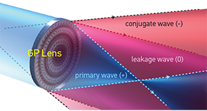 [Michael J. Escuti and Phil Saunders]
Regardless of the implementation, there’s an important caveat: no matter how great the material’s nominal phase-shift range, the phase-shift gradient, |∇δ|, is limited by physical parameters—that is, phase across a GPH can vary in space only as rapidly as the physical implementation can support without producing parasitic dynamic-phase effects or haze. Thus far, in our lab’s work with photo-aligned liquid crystals, this limit has been |∇δ|max ≈ π/μm.
Some GPH applications
GPHs have been used for more than a decade by astronomers—particularly in coronagraphs, the high-contrast imaging of exoplanet systems—within visible and infrared wavelength range (500 to 5,000 nm). Multiple coronagraphs have been built employing GPHs to generate elaborate point-spread-functions to redistribute or block the brilliant starlight, so that the faint light from the planetary region around the star can be observed and studied. Some of these use GP vortex phase plates, with a phase profile proportional to azimuth angle; others use GP apodizing phase plates with a much more complex nonlinear phase. When placed in the pupil plane, these latter elements yield PSFs with dark holes such that exoplanets can be efficiently detected and spectrally characterized.
GP prisms (polarization gratings) act as a kind of diffractive polarization beam splitter with high efficiency and high polarization extinction ratio. In a polarization conversion system, they have been used to convert unpolarized light to linear polarization with up to 90 percent efficiency. In nonmechanical beam-steering applications, they can be used as thin-film beam deflectors in a compact and efficient assembly; they also are used in imaging polarimetry and very high-resolution spatial heterodyne interferometry.
High-quality GP lenses at broadly useful wavelengths are only just now being reported in the literature, and commercial development is underway. Such GP lenses will prove highly relevant to any light management system that would benefit from efficient, thin lenses, including achromatizing refractive lenses used in polarized-light imaging or incorporating these elements into achromatic Fourier transform lenses.
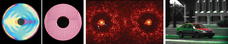 GPHs in action: (Left) Two generations of apodizing phase plates (left, vAPP; right, gvAPP) used in coronagraphs for masking starlight in exoplanet studies [Otten et al., Opt. Express; North Carolina State University, Leiden University and University of Arizona]. (Center) Complementary PSFs of the star system Beta Centauri observed through the gvAPP at 3.9 µm wavelength (arrows indicate two stars) [University of Arizona and Leiden University at the 6.5 m Magellan Clay telescope]. (Right) Color fusion image from a polarimeter based on polarization gratings, showing angle and degree of linear polarization [University of Arizona and North Carolina State University].
The new fabrication techniques discussed earlier should continue to improve and widen these applications—and create new opportunities for using GPHs. More complex GPH phase profiles are also being developed to generate various types of holographic images, including synthetic images of a spot array, aircrafts, faces and logos. We anticipate intense future work in this area. GPHs have at least two advantages over conventional holographic techniques for such applications: broadband (RGB) high efficiency and dramatically reduced multiple-order parasitic images.
We believe this is only the beginning, and that many new components and systems stand to benefit from the combination of performance, versatility and form factor that GPHs bring to the table—a combination that, during IYL 2015, brought such colorful artistry to the arches of Amsterdam’s “Rainbow Station.”
Michael J. Escuti, Jihwan Kim and Michael W. Kudenov are with the Department of Electrical and Computer Engineering, North Carolina State University, USA. MJE is also co-founder and principal at ImagineOptix Co., which is commercializing GPH technology.
References and Resources
-
R.W. Batterman. “Falling cats, parallel parking, and polarized light,” Stud. Hist. Philos. M.P. 34, 527 (2003).
-
C. Oh and M.J. Escuti. “Achromatic diffraction from polarization gratings with high efficiency,” Opt. Lett. 33, 2287 (2008).
-
P.F. McManamon et al. “A review of phased array steering for narrow-band electrooptical systems,” Proc. IEEE 97, 1078 (2009).
-
M.W. Kudenov et al. “White-light channeled imaging polarimeter using broadband polarization gratings,” Appl. Opt. 50, 2283 (2011).
-
J. Kim et al. “Efficient and monolithic polarization conversion system based on a polarization grating,” Appl. Opt. 51, 4852 (2012).
-
G.P.P.L. Otten et al. “Performance characterization of a broadband vector apodizing phase plate coronagraph,” Opt. Express 22, 30287 (2014).
-
N. Yu and F. Capasso. “Flat optics with designer metasurfaces,” Nat. Mater. 13, 139 (2014).
-
J. Kim et al. “Fabrication of ideal geometric-phase holograms with arbitrary wavefronts,” Optica 2, 958 (2015).
-
G. Zheng et al. “Metasurface holograms reaching 80% efficiency,” Nat. Nanotech. 10, 308 (2015).
-
M. Shipman. “The science and engineering behind Amsterdam’s Rainbow Station,” https://news.ncsu.edu/2014/12/rainbow-station/
-
J. Males. “MagAO+Clio’s new apodizing phase plate coronagraphs,” https://visao.as.arizona.edu/press/magaoclios-new-apodizing-phase-plate-coronagraphs/