
A massive network of fiber optic cables lies deep under the seas across the Earth. The cables allow us to quickly send our emails and videos, and connect our browsers and phone calls to sites in far-away lands. This network isn’t new. Submarine data cables date back to 1850, when the first international telegraph cable (with a capacity of 10 words per minute) spanned the channel between England and France. As early as 1901, telegraph cables crisscrossed the oceans and connected all the continents except for Antarctica.
Subsequent cable generations included upgrades to telephone cables and data communications cables. Analog coaxial cables of steel-wrapped copper were widespread under the oceans beginning in the 1950s. The bandwidth of analog cable increased quickly in the 1960s and 70s, but the highest capacity systems required electrically powered repeaters to boost the signal every 6 to 9 kilometers, making them very expensive to install across oceans.
Starting in 1988, a massive 10-year build-out replaced the vast majority of these copper network cables with long-haul fiber optic cables. Today virtually all of the undersea long-haul communication cables are optical, as are land-based ones. Submarine data cables handle more than 95 percent of IP voice and data traffic between countries and continents, and 100 percent of international Internet traffic. Users in the United States, Europe and other well-connected regions often take for granted the ease of global communications.
The underwater cable network is a critical component to global commerce, and it’s growing. Spurring this growth is ever-increasing IP traffic, demand for higher bandwidth at reduced deployment cost and the need for additional routes and redundant cable systems that ensure resiliency. According to a comprehensive market research report by Global Industry Analysts, cumulative global installation of submarine optical fiber cable is projected to reach two million kilometers by 2018, up from just over a million kilometers in 2009.
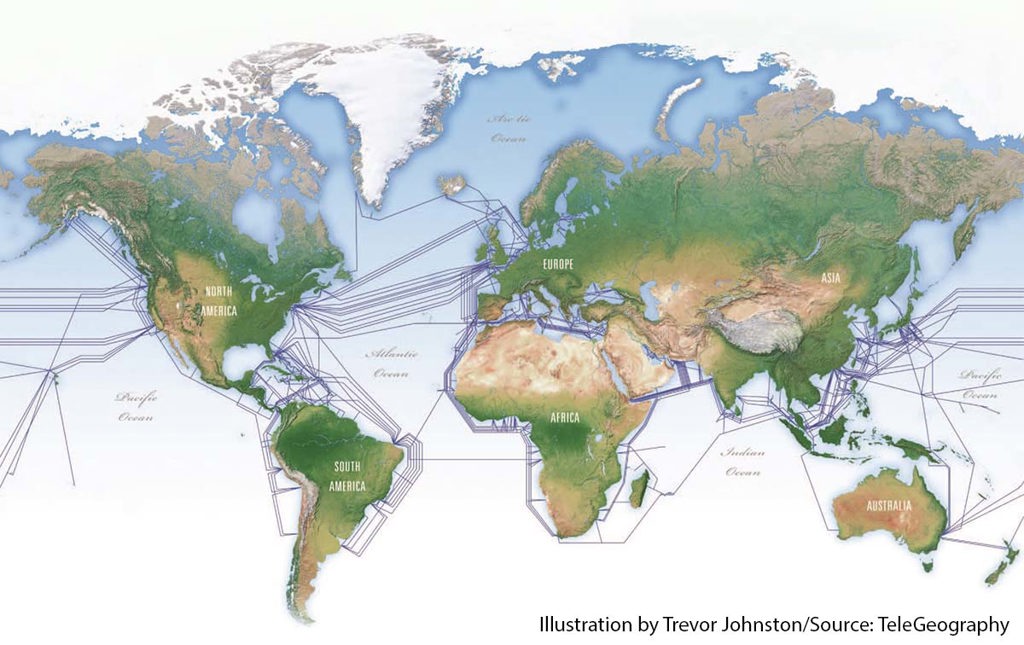
2013 submarine cable map. [Enlarge image]
Capacity and design
A typical submarine communications cable has a diameter of 17 mm—about the size of a garden hose—for deep-water cable, to 70 mm for heavily armored cable in shallower water. The shallower the cable, the thicker its armor must be. The fiber optic core is typically encased in high-tensile-strength galvanized steel wires surrounding a copper sheath, surrounded by more layers of steel armor and polyethylene insulation.
The longest submarine cable is the Southeast Asia–Middle East–Western Europe (SEA-ME-WE 3) system stretching 39,000 kilometers from Norden, Germany, to Keoje, South Korea. The system connects 33 different countries with 39 landing points. The SEA-ME-WE 4 submarine cable project, completed in December 2005, covers approximately 20,000 kilometers of links from Marseille, France, via the Middle East and the Indian subcontinent to Tuas, Singapore. The new system was designed to complement and add redundancy to SEA-ME-WE 3, and uses dense wavelength division multiplexing technology to achieve 1.28 Tbit/s capacity for telephone, Internet, multimedia and various other broadband applications.
Redundant links
One of the biggest challenges facing the submarine optical network is that many parts of the world are still vulnerable to disruptions in service due to lack of redundancy. Network architectures use redundant bidirectional links between stations, like roadways and water distribution systems, to prevent loss of use in the event that the signal from a link or station is lost. These so-called “self-healing” rings will loop traffic through operational parts of the ring when the shortest link is disrupted.
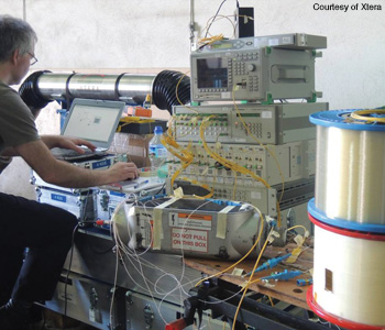
An Xtera engineer tests an underwater network cable repeater before loading it onto the ship.
The cable industry is used to repairing faults, which happen less frequently than in terrestrial networks but take much more time to reach and repair (typically one to four weeks, compared with one day on land). Transatlantic cables require dozens of repairs each year, but the United States and Europe have ample redundancy, so a single cable failure is hardly noticeable. Cuts to cables in bottleneck areas like the Suez Canal (for cables connecting Europe to the Middle East, Asia and East Africa), however, can slow down or even completely disrupt service for weeks.
The most common threat to submarine cables are shipping and fishing activities. Roughly 70 percent of cable damage from anchor-dropping and trawling occurs in water less than 200 meters deep. While some countries designate “anchor-free” zones near cable routes, accidents happen. And some interruptions appear to be intentional attacks, the motivations of which are difficult to discern.
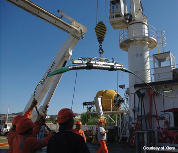
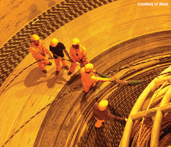
A crew loads an optical repeater from the dockside port to the cable deployment ship in a sea trial off the coast of France in the Mediterranean.
One of the worst service disruptions to date occurred 19 December 2008, when France Telecom announced that three major subsea optical cables were cut by either a ship’s anchor or bad weather. The cables included the FLAG Telecom cable, SEA-ME-WE 3 and SEA-ME-WE 4, linking Alexandria, Egypt; Sicily and Malta. The damage disrupted 75 percent of the Internet service connecting Europe with the Middle East, North Africa and India until it was repaired on 31 December. Rerouting of communications to other areas caused significant slowdowns in Internet connections and telephone calls.
A more recent incident involving three men suspected of scuba diving down to cut the SEA-ME-WE 4 cable off the coast of Egypt occurred in March 2013. Many experts feel that deliberate sabotage of underwater cables is far-fetched or unlikely, but the degree to which underwater-cable bottlenecks have the potential for serious disruptions is causing providers to look for alternate ways to connect the continents. According to an April 2013 report by TeleGeography, demand for capacity between Europe and Asia via Egypt ballooned 87 percent per year between 2007 and 2012. Yet planners of the SEA-ME-WE 5, by some accounts the granddaddy of all Europe-to-Asia submarine cables, are considering bypassing Egypt completely. Plans include terrestrial routes, or new submarine routes via South America, South Africa and even the Arctic.
And why not route cable through the Arctic? Toronto-based Arctic Fibre proposed a 15,700-km subsea backbone cable connecting Tokyo and London, passing through the Bering Strait and along the Northwest Passage through the Canadian and Alaskan arctic. According to the company, the route is 4,280 kilometers shorter than current low-latency routes through the Suez Canal. With steadily shrinking polar ice caps, deployment of such a system is possible in warmer months, although it would be difficult to repair it 12 months a year. The estimate to build the 24-Tbit/s capacity Arctic Fibre network is $620 million. Arctic Fibre is working to raise $220 million in equity funding from investors for a cable with 80 wavelengths at 100G. If successful, the route is slated for operation in January 2016.
Submarine cable vs. Satellite
Why does most of our data still travel via submarine cables instead of satellites?
- Data traffic through undersea optical fiber cables offer advantages in terms of reliability, security, capacity and cost.
- Microwave satellite signals take about 0.2 seconds to travel roundtrip from the ground to an orbiting satellite, while optical submarine cables can send data across the Atlantic in 1/20th of that time, resulting in lower latency.
- The microwave spectrum available to satellites is limited, while the spectrum available for optical communications has more room for increasing IP traffic.
- Wavelength division multiplexing technology increases the capacity carried by single fibers and thereby reduces the number of cables required; deploying fewer and smaller cables is then more cost efficient for the amount of capacity versus the high cost of deploying and maintaining satellites.
Natural causes
Natural disasters such as mudslides and typhoons are also a threat to undersea fiber. A magnitude-7 earthquake in Taiwan on 26 December 2006 damaged eight submarine cables, catastrophically cutting off communication to Hong Kong, South East Asia and China. Because Taiwan is located in a central point in Asia’s underwater network, a large population of cables is concentrated in the middle of a major seismic belt. The magnitude-9 earthquake and resulting tsunami in March 2011 off the coast of Japan that savaged the Fukushima nuclear power plant also damaged about half of the existing transpacific cables. Fortunately, the other half of the cables were undamaged so network operators were able to reroute traffic to minimize complete outages.
In June 2013, the Southeast Asia-Japan Cable (SJC) consortium announced an underwater fiber cable deployment that shores up reliability in the event of earthquakes. SJC, supplied by TE SubCom and NEC Corporation, links the countries or territories of Brunei, China, Hong Kong, Japan, Singapore and the Philippines, including the option to link with Thailand. SJC is an 8,900-km cable system that could further extend to 9,700 kilometers. Costing around $400 million, SJC consists of six fiber pairs with the initial design capacity of 28 Tbit/s to meet bandwidth-hungry applications such as Internet TV, online gaming and enterprise data exchange. The cable’s design capacity enables simultaneous streaming of up to 30 million high-definition videos. According to Ooi Seng Keat, spokesperson for the SJC consortium and vice president of SingTel, the SJC route avoids the earthquake zone in North Asia, enhancing reliability in the event of a network interruption.
The route of NTT Communications Corporation’s (Tokyo) Asian Submarine-cable Express (ASE), a 40G per wavelength cable with a max capacity of 15 Tbit/s, is also designed to bypass high-risk earthquake and typhoon zones to avoid the damage that has occurred almost every year since 2006 near Taiwan, which sits on a line between Hong Kong and Tokyo.
“The shortest distance between two points is not always a straight line,” says Junta Nakanishi, director of network engineering at NTT, referring to the way the new line is routed to avoid the earthquake-prone Bashi channel south of Taiwan. ASE covers 7,800 kilometers to link Japan with the Philippines, Hong Kong, Malaysia and Singapore. Rather than traveling the shortest, straightest line between Hong Kong and Tokyo, the cable is routed around areas where undersea earthquakes have disrupted service frequently in the past. Going a little deeper into the water off of coastal shelves may help prevent storm damage.
Hero transmission
Fiber capacity is determined by the number of wavelengths or “carriers” and the data rate of each carrier (e.g., 150 carriers at 100G each provide 15 Tbit/s of capacity in the fiber). With a higher bandwidth spectrum, it’s easier to multiplex many wavelengths down a single fiber. The cable and repeater typically support four or six fiber pairs. In a fiber pair, one fiber is used for one direction of transmission, the other fiber for the other direction. The total cable capacity is the fiber capacity times the fiber pair count. For example, in a cable equipped with four fiber pairs and repeaters that can handle up to 150 carriers, the capacity is 4 × 15, or 60 Tbit/s.
Just three years ago at the OFC 2011 meeting, the standard capacity to meet for submarine systems being built and upgraded was 40G. As of early 2014, 100G is the new standard in fiber data rates for each carrier to achieve, submarine or otherwise. The tide changes quickly. What will 2014 and beyond bring to submarine optical communications?
Workers aboard a cable ship coil a cable with repeater onto a large spool for an at-sea test.
The next step is 400G. In April 2013, subsea cable system provider TE SubCom (Eatontown, N.J., U.S.A.) reported a lab demonstration of 53 carriers at 400G over a record 9,200 kilometers using digital coherent transponders to compensate for dispersion and polarization mode dispersion (PMD). Neal Bergano, managing director of system research and network development at TE SubCom, predicts that systems installed in the next year or two will have 10 times the capacity of systems installed a few years ago—which would be 400G. This demonstration is closer to a “hero” experiment than a real long-haul subsea cable system ready for commercial service. But such records are often predictive of the technology that will be the standard of installation in the field in a few short years.
The challenge remains to pack as much signal capacity as possible into a narrower bandwidth channel. In July 2013, NTT announced the deployment of a 100G transpacific submarine cable linking the United States and Japan. The cable features the company’s new digital coherent technology, which increases the PC-1 cable system’s capacity by more than 2.5 times to 8.4 Tbit/s. The existing PC-1 optical submarine cable, the shortest transpacific link, is a ring 21,000 kilometers long that crosses the Pacific twice, with landing stations in Ajiguara and Shima, Japan, as well as Washington and California in the United States.
The 100G digital coherent technology combines coherent detection and digital signal processing to improve spectral efficiency, a measure of how many information-carrying channels can be packed into a given bandwidth, through multi-level modulation, including phase modulation and polarization multiplexing. Wavelength division multiplexing enables a high capacity of more than 15 Tbit/s by squeezing multiple signals down single fibers, enabling thinner and lighter cable. By the end of 2014, the same 100G optical transmission technology also will be deployed in NTT’s ASE, which links major cities in Asia via the shortest possible route with low latency.
We can also expect new submarine routes and higher-capacity cables along existing routes in the near future. The South Atlantic will be a hot point. GlobeNet, SAM-1 and Consortium cables will connect Brazil, and even higher-speed systems such as the 100G Seabras-1 cable will connect the United States to Brazil in 2015 to expand capacity in Latin America. Two more cable systems will improve connectivity in the South Atlantic within the next three years: the South Atlantic Express will run from Fortaleza, Brazil, to Melkbosstrand, South Africa; Angola Cables will connect Brazil directly to Angola. Many more systems are planned to connect South America and Africa to the rest of the world in the near future.
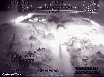
An underwater submersible camera inspects the repeater after burial in a sea trench.
Improving repeaters
The practical solution to effectively send a signal across the ocean without degeneration is to more effectively repeat it so that it travels further without increasing cost. Xtera Communications (Dallas, Tex., U.S.A.) announced in April 2013 the launch of a next-generation optical repeater for subsea cable systems. A modular optical design allows the amplifiers to be tailored to different system requirements, from short regional systems to very long transoceanic systems; another variant offers an optical bandwidth extending beyond the normal erbium-doped fiber amplifier (EDFA) C-band. High efficiency drivers allow tunable line current to reduce overall voltage. The design enables simplified manufacturing without sacrificing reliability and value. The repeater is constructed from marine-grade titanium, resulting in a lightweight but strong unit that can be deployed to water depths of 8 kilometers. The company successfully tested the repeater in the shallow waters of the Mediterranean off the coast of France in May 2013.
Unlike the cable itself, the biggest challenge to a repeater is its handling. “The key is a miniaturized amplifier, with a spectrum width exceeding 50 nm—that is, about 70 percent higher bandwidth than conventional EDFAs,” says Bertrand Clesca, head of global marketing at Xtera. The repeater is longer and narrower than standard repeaters (which are about 25 cm in diameter). The armor and interior of the repeater is jointed so that it can be bent for coiling onto the large cable spools that store the cable on the ship before deployment. The coiling capability is also necessary for deployment via the stern sheaves of the cable ship and for recovery with the cable ship winch. Streamlining the repeater reduces the complexity of deployment, thereby reducing the expense to install the network. The small diameter and jointed casing also enable the repeater to pass directly through the “plough” or plow—the large tractor used to bury the cable on the seafloor—making for easier handling.
“A repeater is exposed to maximum stresses and constraints when it’s loading from the cable factory to the cable ship, when it’s deployed at the stern of the cable ship, when it’s buried, and when it is recovered for repair,” says Clesca. “When the repeater is installed at the sea bottom, the temperature and pressure are stable and the biggest threats are the same ones affecting cable: fishing, anchoring, abrasion and erosion.”
For transoceanic spans of 7,000 to 12,000 kilometers, the repeater spacing is about 60 kilometers. For shorter hauls of 600 to 3,000 kilometers with modest long-term capacity requirements, the repeater spacing can be extended to 120 kilometers or more. The specified lifetime for a repeater is 25 years, which is comparable to components in the space industry. Amidst all this very sophisticated technology, the shipside procedures for laying and recovering the cable remain very traditional.
“I’ve always found it interesting that the same ropes and grapnels used a century ago are still used today—but they are combined with high-end dynamic positioning systems and very sophisticated photonics based on lasers and fibers,” says Clesca. With this combination of traditional and space-age technology, submarine networks are racing to connect our future.
Valerie C. Coffey is a freelance science and technology writer and editor based in Acton, Mass., U.S.A.
References and Resources
- R.L. Carter et al. Submarine cables and the oceans: Connecting the world. UNEP-WCMC Biodiversity Series No. 31. ICPC/UNEP/UNEP-WCMC (2009).
- Global Industry Analysts. “Submarine optical fiber cables: A global strategic business report” (2013).
- S. Bookman. “Submarine cable operators hunt…political turmoil,” FierceTelecom.com (18 April 2013).
- Xtera Communications Inc. “100G field trial on a transatlantic subsea cable system,” www.xtera.com/en-US/Resources/Videos (May 2013).