
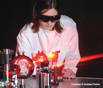
 Angela Dudley creates OAM light fields with a spatial light modulator.
In the late 1980s, Jim Durnin and colleagues outlined the concept of the Bessel beam—a theoretical non-diffracting light beam with an infinite number of rings that can cover an infinite distance and requiring an infinite amount of power. Today, researchers can make quasi-Bessel beams that come close to meeting the theoretical beam’s impressive parameters. Such beams are used in a variety of applications, including optical trapping and tweezing, the drilling of high-precision holes, and controlling the propagation of ultra-short pulses in dispersive media.
Now, there is growing interest in the scientific community in using Bessel beams as information carriers. They seem ideal for the job—the multi-ringed beams retain their shape over extended propagation distances. But how do we load them with data and access the information without wasting photons? Digital spiral imaging and mode sorters may provide a solution.
Creating a Bessel beam
The most common way to create a Bessel beam is with an axicon—a conical lens that can be used as a refractive or diffractive optic or as a digital hologram written to a spatial light modulator. Since Bessel beams have the far-field pattern of an annular ring, they can also be created by combining an annular slit (which may be digital) and a Fourier transforming lens, much as Durnin did all those years ago. There are various tools available for creating zero-order Bessel beams, high-order Bessel beams and arbitrary superpositions as well. As shown by Carlos López-Mariscal, virtually any light pattern can be made quasi–non-diffracting because all quasi–non-diffracting light has the far-field amplitude profile of an annular ring, and the ring phase can be considered as a degree of freedom in the design. This concept has been applied to create complex light patterns with shapes that do not change over long propagation distances.
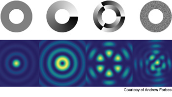 Annular rings and quasi–non-diffracting fields: Four digital annular rings encoded with phase profiles (top) to produce the corresponding quasi–non-diffracting fields (bottom, left to right): a zero-order Bessel beam; a higher-order Bessel beam (l = 1); a superposition of two higher-order Bessel beams (l = +3 and –3); and a random non-diffracting beam.
High-order Bessel beams are considered a type of light field that can carry orbital angular momentum (OAM). Whole optical beams and single photons have OAM—it’s associated with the field’s spatial profile. Therefore, this degree of freedom can be used to create custom fields for carrying information encoded in the OAM basis. More generally, you could use any set of spatial modes as the basis, but you need two indices to describe the individual mode.
For commonly used Laguerre-Gaussian modes, the OAM information is contained in the azimuthal index, l, while data about the radial mode is in the discrete radial index, p. For Bessel beams, you also need the azimuthal index, but instead of the discrete radial index, you need the continuous radial wave vector, kr, to retrieve the spatial modes. Unlike the two orthogonal states of polarization, spatial modes have (in principle) an infinite state space to play with.
Challenges
Researchers are pouring considerable effort into exploiting the extra degrees of freedom that spatial modes provide, both for classical communication—mode-division multiplexing—and for storing information in higher-dimensional quantum states of entangled photons for secure quantum communication. The challenges include putting information into the field by creating custom superpositions, finding communication channels that have minimal cross-talk between the modes, and getting the information out of the modes. For classical mode multiplexing, putting information into spatial modes is as simple as creating appropriate holograms and then diffracting them for the desired combinations.
In quantum state engineering, Bessel modes allow access to more dimensions while retaining the properties that make them interesting—their stability. But how do you get the data out of them without wasting the information-carrying photons? Put another way, how do we access information encoded in many different states when only one state may be sampled at a time?
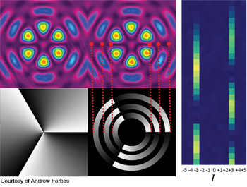 Using holograms to unravel data in Bessel beams: A pure azimuthal hologram (bottom left), annular slit hologram (bottom right) and the unraveled information (right). The azimuthal decomposition on a superposition of two high-order Bessel beams of azimuthal indices +3 and -3, by a ring-slit decomposition.
Unraveling the message
The answer is to unravel the unknown field into its constituent parts and in both indices. This extrication must reveal the amplitude and phase of each component in the Bessel beam superposition, preferably in a manner that allows all states to be observed simultaneously.
Rather than reinvent the wheel, it makes sense to borrow from the pattern recognition community and do a modal decomposition of the Bessel beam with appropriate match filters. With today’s liquid crystal devices (spatial light modulators), the filters can be programmed as holograms. The devices are rewritable at video refresh rates so that the sampling can be done almost in real time.
One way to do this is to exploit high-order Bessel beams, Jl(krr) exp(ilφ), which have a concomitantly high azimuthal index, l, that can expand any unknown field into the basis of angular harmonics, ∑al(r)exp(ilφ). Since the harmonics are independent of spatial scale and orthonormal over the azimuthal plane, we can find the azimuthal indices of any superposition field. The coefficients, al, contain both the amplitude of the original field’s given azimuthal mode and the phase delay relative to the other modes. For example, if a third-order Bessel beam is present in the unknown field, it will result in a signal for the a3 (l = 3) mode.
To experimentally implement this technique, we would program the complex conjugate of the mode as the match filter. This filter is nothing more than a hologram of a spiral phase or a forked grating if a blazed grating is added. Continuing with the example of a third-order Bessel beam, the hologram would depict exp(–i3φ). However, this would not return the radial information of the mode. The signal needs to be determined radially—i.e., a3(r), for each radial position, r. We can do this by scanning a digital annular slit across the beam—otherwise known as digital spiral imaging. The annular slit is maintained at a small width but varied in its radial position on the field. As the annular slit is scanned in the radial direction, the amplitude and phase information is returned. This is repeated for each azimuthal mode (l = 1, 2, 3, etc.). The result is an unraveling of the Bessel beams contained in the original beam.
This filtering technique works because all the physical properties of the field can be inferred, such as phase, wavefront, vortices and orbital angular momentum density, but only one state can be examined at a time and so many photons are wasted in the process. For instance, if the original field did not have an l = 3 component, all the sampling at l = 3 would result in lost information.
One way to avoid information loss is to execute a clever optical trick—converting the azimuthal phase variation of the Bessel beams into a linear phase variation. This works for any beam with an azimuthal phase variation and was initially demonstrated with Laguerre-Gaussian beams. Once the azimuthal phase is converted to a linear phase, the modes can be sorted by a single lens because lenses map different incoming ray angles (linear phase ramps) to different lateral positions in the focal plane. The position in this plane is proportional to the l index of the incident beam.
This mode sorter works by transforming an annular ring of light and conformally mapping it to a line by passing it through two custom optics. Consider a third-order Bessel beam in the far field: The annular ring’s phase will vary from zero to 6π (2πl) around the ring. If this ring is mapped to a line, then the line will have this phase variation across it—in other words, it will look like a tilt introduced to the phase front. The last step is to pass this tilted light through a lens to map the incoming tilt angle—which depends on the original beam’s azimuthal component—to a unique position. This principle works even if the incoming beam has many azimuthal components, since each maps to its own unique position (e.g., in the horizontal direction). What we see are spots of light at various positions in the horizontal direction.
|
|
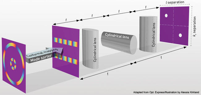
If the output from the mapping process is passed through two lenses to form an image, then the field’s radial information will be contained in the vertical position of the spots. Three cylindrical lenses are used to accomplish both tasks at once. One lens is rotated 90 degrees relative to the others so that the horizontal plane produces a Fourier transform and the vertical plane produces an image. On a 2-D detector, the vertical and horizontal locations of the spots tell you exactly what you want to know—the radial scale and azimuthal index of the field. The information is decoded in a manner that does not waste photons or require any a priori information of the field.
The end of the story?
 Optical transformation of an azimuthal phase (red circle) to a linear phase (red line).
Both the digital spiral imaging and mode sorting techniques can be used to efficiently decode Bessel beams, but each method has drawbacks. In performing a modal decomposition on Bessel beams, one must incrementally sample azimuthal modes in the field—but multiplexing the necessary holograms makes it easy to extract all azimuthal modes of interest in a single measurement. As with most modes generated with digital holograms, there is a practical limit to the number that can be multiplexed into a single hologram. Mode sorting does not suffer from this shortcoming; it allows one to sort a range of OAM modes in a single measurement procedure. However, there’s slight cross-talk between neighboring OAM modes that results in false detections. The cross-talk between neighboring modes can be reduced by separating the modes into odd and even ports before entering the mode sorter.
Apart from developing efficient techniques for detecting Bessel beams, the creation of these modes can be exploited by coupling their OAM to their spin angular momentum (SAM), thus generating modes encoded in both OAM and SAM. Together with the radial information, this produces modes that have two high-dimensional state spaces plus one 2-D state space, which will prove useful in quantum communication and information systems. So rather than the end of the story, these techniques are perhaps only the beginning.
|
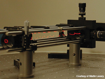
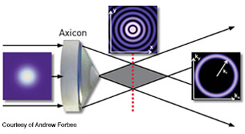 A Bessel beam (near field) and an annular ring (far field) are formed when an axicon is illuminated with a Gaussian beam.
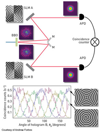
Martin Lavery and Miles Padgett are with the School of Physics and Astronomy, University of Glasgow, Scotland. Angela Dudley and Andrew Forbes are with the National Laser Centre, CSIR, South Africa.
References and Resources
-
D. McGloin and K. Dholakia. “Bessel beams: diffraction in a new light,” Contemp. Phys. 46(1), 15-28 (2005).
-
G.C.G. Berkhout et al. “Efficient sorting of orbital angular momentum states of light,” Phys. Rev. Lett. 105(15), 153601 (2010).
-
C. Lopez-Mariscal and K. Helmerson. “Shaped nondiffracting beams,” Opt. Letters 35(8), 1215-17 (2010).
-
M. Mazilu et al. “Light beats the spread: non-diffracting beams,” Laser Photon. Rev. 4(4), 529-47 (2010).
-
A.M. Yao and M.J. Padgett. “Orbital angular momentum: origins, behaviour and applications,” Adv. Opt. Photon. 3(2), 161-204 (2011).
-
M. Duocastella and C.B. Arnold. “Bessel and annular beams for materials processing,” Laser Photon. Rev. 6(5), 607-21 (2012).
-
I.A. Litvin et al. “Azimuthal decomposition with digital holograms,” Opt. Express 20(10), 10996-11004 (2012).
-
M.G. McLaren et al. “Entangled Bessel-Gaussian beams,” Opt. Express 20(21), 23589-97 (2012).
-
A. Dudley et al. “Efficient sorting of Bessel beams,” Opt. Express 21(1), 165-71 (2013).
-
M. Lavery et al. “Efficient measurement of an optical orbital-angular-momentum spectrum comprising more than 50 states,” New J. Phys. 15(1) 013024 (2013).