
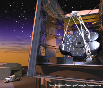
 Artist’s concept of the Giant Magellan Telescope. The seven primary mirror segments form a single 25-m parent surface, while the seven matching secondary mirror segments form a 3.2-m concave surface.
In August 2006, the Steward Observatory Mirror Lab cast a 3.75-m mirror under the stands of the University of Arizona football stadium. Twenty years earlier, this mirror could have become the primary mirror for the sixth largest optical telescope in the world. Today, it’s a piece of the test optic system that is guiding the manufacture of the 25-m primary mirror for the Giant Magellan Telescope (GMT).
The GMT is part of a wave of new, ever-larger telescopes that first came on the astronomical scene in the early 1990s. Astronomers will use them to study distant planets, stars, galaxies and black holes. In some cases, their goal is to understand the structure and evolution of the objects themselves. In others, they will study objects to reveal the fundamental structure and evolution of the universe as a whole. A large telescope can capture supernovae (catastrophic explosions of stars that have run out of nuclear fuel) at such great distances that scientists can use the images to trace the expansion and acceleration of the universe. And slight distortions in the images of distant galaxies can map the distribution of the invisible dark matter that appears to make up over 80 percent of the universe’s mass.
With their unprecedented sensitivity and angular resolution, these telescopes open new windows onto the universe. Sensitivity scales with area, and resolving power scales with diameter if a coherent wavefront can be maintained. One quest that demands all of the sensitivity and resolution that can be squeezed out of a telescope is the direct imaging of planets around other stars. Several hundred extrasolar planets have been detected by their star’s tiny oscillation around the common center of mass, or the slight darkening that appears when they pass in front of the star.
Direct imaging is much more difficult because the planet is so close to the billion-times-brighter star. Just last year, astronomers reported the first images of several large planets orbiting other stars—planets several times larger than Jupiter with orbits similar to those of Uranus, Neptune and Pluto. The new generation of telescopes, including the GMT, will be able to image mature planets down to about Jupiter’s size, with orbits as small as Earth’s, as well as smaller Earth-like planets that are young enough to glow in the infrared as their gravitational energy leaks out. Direct imaging will one day lead to spectroscopy and the ability to detect oxygen in a planet’s atmosphere, the signature of life.
A brief history of telescopes
A previous burst of telescope development occurred during the early 20th century, when George Ellery Hale led efforts that culminated in the 60-in. and 100-in. telescopes on Mt. Wilson and the 200-in. Hale Telescope at Palomar. Following the construction of the 200-in. device in the 1930s and its commissioning in 1948 after the war, growth in telescopes was put on pause for almost half a century. Detectors improved and new wavebands opened up, but mass, flexure and thermal inertia proved serious obstacles to larger mirrors.
A mirror needs to be stiff enough to hold its shape against the wind and (at least in the mid-20th-century paradigm) against its own weight. But that stiffness implies mass, which drives up the mass and cost of the whole telescope structure. It also makes the mirror a huge repository of thermal energy that can’t be shed fast enough to follow changes in nighttime air temperature, and that causes the same kind of turbulence and image blurring we see when looking across a hot pavement.
The mirror challenge was finally overcome in the late 1970s and 1980s by three groups in three different ways. Jerry Nelson, then at the University of California at Berkeley, led the development of segmented mirrors, in which a large primary mirror is synthesized by dozens or even hundreds of small segments. The difficulties in making and controlling the large mirror are traded for the challenge of keeping the segments aligned to a fraction of a wavelength.
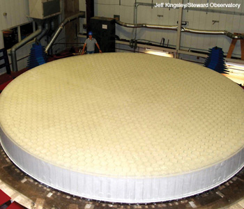 The first GMT segment rests on the furnace hearth after a successful casting. The honeycomb sandwich mirror is a single piece of glass containing 1,700 hexagonal cavities. The ceramic fiber mold that forms the cavities is still inside the mirror at this point, but it is washed out in a later operation.
This concept has worked superbly in the twin 10-m Keck telescopes, and it is used for several other 10-m-class telescopes in use and under construction. Looking to the next generation of telescopes, two telescopes have been designed with one-meter-class segments—the Thirty Meter Telescope, which is being developed by the University of California, Caltech and partners, and the 42-m European Extremely Large Telescope.
Another solution to the problem of massive mirrors came from Ray Wilson and colleagues at the European Southern Observatory (“southern” because their telescopes are in Chile), who realized they could turn the flexibility of a thin mirror into an advantage by supporting it on an active system of computer-controlled actuators. This concept, in the form of mirrors 8 m in diameter and 175-200 mm thick, is the basis for ESO’s Very Large Telescope (four telescopes), the two Gemini Telescopes and the Japanese Subaru Telescope.
Today, all large mirrors use Wilson’s active optics concept. They’re supported by 100-200 actuators and actively controlled with feedback from sensors that measure the shape of the reflected wavefront. This is a slow correction—because of the mirror’s huge inertia and the need to average atmospheric fluctuations out of the wavefront measurement—but it can have an amplitude of several microns.
The third solution, now the basis for the GMT, was Roger Angel’s development of honeycomb sandwich mirrors at the University of Arizona. The mirrors’ structure, formed by melting the glass in a complex mold, is the 2D version of an I-beam, so these mirrors are about eight times stiffer than solid mirrors with comparable mass. They bend less due to weight and wind, and their short thermal time constant lets them follow the changing air temperature at the telescope. In order to reduce telescope dimensions, the Arizona mirrors have shorter focal lengths than other large mirrors. The Mirror Lab uses a dramatic spin-casting process to produce the honeycomb structure and the deep curvature, then refines the surface by machining and polishing. The figure above shows the GMT mirror right after its casting.
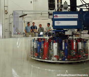 An active polishing disk accommodates the segment’s 14 mm of aspheric departure. Computer-controlled actuators bend the 1.2-m disk as it moves across the segment, so the polishing surface always matches the local shape of the desired mirror surface.
Honeycomb sandwich mirrors
Beginning in 1983, the Mirror Lab cast and polished a number of mirrors of 1.8 m diameter—then 3.5 m, 6.5 m and finally 8.4 m. The 6.5-m mirrors are in the MMT telescope in Arizona and the twin Magellan telescopes at Las Campanas Observatory in Chile. The Large Binocular Telescope on Mt. Graham in Arizona is the world’s largest with two 8.4-m primary mirrors on a common mount. The short focal lengths of these mirrors (the LBT mirrors are f/1.1) forced the lab to develop technology that allows the efficient manufacture of highly aspheric mirrors. After spin-casting, the next development was an active polishing disk that changes its shape continuously to match the local curvature as it moves across the surface.
Optical testing is also an interesting problem for very aspheric mirrors. The standard technique is phase-measuring interferometry, in which the full mirror surface is illuminated with a coherent beam, and the reflected wavefront interferes with an accurate reference wavefront, ultimately giving a contour map of the surface with a resolution of about λ/100. The challenge is that the illuminating wavefront must match the desired mirror surface; this wavefront is the template that the surface is compared with. Any error in the template causes an error in the mirror shape. The interferometer’s illuminating wavefront is typically spherical, and a set of optics known as a null corrector transforms it into a template wavefront of the right shape.
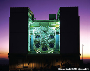 Progression of telescopes using lightweight mirrors: The original Multiple Mirror Telescope formed a 4.5 m aperture with six 1.8-m mirrors.
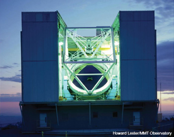 The new MMT, in the same enclosure, replaced the six mirrors with a 6.5-m honeycomb sandwich mirror.
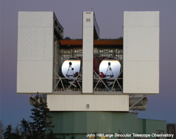 The Large Binocular Telescope combines the light from two 8.4-m mirrors.
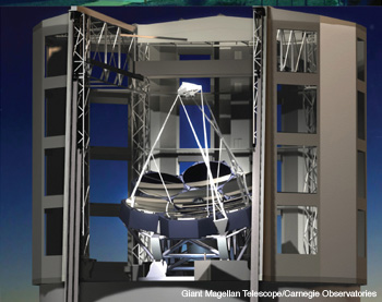 The Giant Magellan Telescope forms a 25-m aperture with seven 8.4-m segments.
The null corrector itself can be difficult to make and measure. The poster child for this difficulty is the Hubble Space Telescope’s primary mirror, which was polished to match the wrong template to exquisite accuracy. Since then, the astronomical optics community has been hyper-sensitive about the need to validate the null corrector. My colleague Jim Burge at the University of Arizona’s College of Optical Sciences has developed a technique in which computer-generated holograms (CGHs) are used as inverse null correctors, effectively mimicking an ideal primary mirror. These guarantee accurate measurements of the Arizona mirrors, including the most aspheric large mirrors made to date, the LBT primary mirrors.
Segments for primary mirrors and adaptive secondary mirrors
While most of the current 8-m-class telescopes use monolithic primary mirrors, no one is thinking about making a monolithic mirror for the next generation of 25- to 40-m telescopes. The new telescopes are segmented, and the only question is what size the segments should be. The primary mirrors for the Thirty Meter Telescope and ESO’s Extremely Large Telescope will use 500 to 1,000 segments of about 1.4 m diameter.
The GMT, on the other hand, will use the largest segments that can be made, which are 8.4-m honeycomb sandwich mirrors similar to the LBT primary mirrors. They guarantee a smooth wavefront over 8.4-m subapertures. The telescope’s 3.2-m secondary mirror is segmented to match the primary mirror, and alignment is controlled with the seven small, agile secondary segments.
The GMT secondary segments are particularly agile because they’re also the deformable mirrors of the adaptive-optics system that will correct wavefront distortions caused by the atmosphere. What appears as twinkling (intensity fluctuations) to the eye shows up as phase variations across a large telescope aperture. A large telescope in space could form images with diffraction-limited angular resolution of about λ/D, or 4 milli-arcseconds for a 25-m telescope at 0.5-µm wavelength.
For a ground-based telescope, however, the resolution-limiting diameter is that over which the wavefront is flat within about a wavelength—typically 15 cm at 0.5 µm at a good mountain site. This limits the resolution to 0.7 arc-second—more than 100 times worse than the potential resolution.
To get around this severe limitation, astronomers have developed remarkable adaptive optics systems that sense and correct for the atmosphere’s effects on the wavefront. Their efforts got a boost when a good deal of military research in this area was declassified in the 1990s. The basic principle of correction is simple: Measure the distorted wavefront and bend the opposite error into a deformable mirror somewhere in the optical system.
The hard part is that the atmosphere is constantly changing, so correction requires a new measurement and a new mirror shape roughly every millisecond for visible wavelengths. The update requirement is relaxed to every few milliseconds for the more-forgiving infrared wavelengths. Most large telescopes have some form of adaptive optics, and most are working in the infrared today. As faster actuators, wavefront sensors and processors are developed, astronomers are gradually pushing the techniques to visible wavelengths.
The adaptive optics system of the GMT builds on the ones developed for the 6.5-m MMT and the LBT, with the secondary mirror segments serving as deformable mirrors. Each 1.1-m diameter segment will be 2 mm thick and supported by about 1,000 voice-coil actuators. This system adds no additional reflections beyond the two that occur in any telescope, an important advantage because every reflecting surface adds thermal noise to the signal, especially at longer infrared wavelengths. The adaptive secondary mirror will help enable the search for warm, young exoplanets in the infrared.
In fact, we expect to be able to see in the infrared even mature Earth-like planets around the nearest stars (if there are any). This detection would go right to the limit of capability. It requires both the resolving power and the infrared sensitivity of a 25-m aperture with an adaptive secondary mirror. For the GMT, the adaptive secondary has the additional advantage of keeping the seven intertwined telescopes aligned and in phase, even if the large primary segments have relative motions of many microns.
Building up to the Giant Magellan Telescope
Not only the adaptive optics system but the entire GMT design follows naturally from the progression of larger telescopes using honeycomb sandwich mirrors. The collecting area increased first by using the largest mirrors possible, and then by combining multiple mirrors for even more powerful systems. The basic mirror design hasn’t changed and comes with mature active support and thermal control systems. These mirrors have produced some of the best images ever obtained without adaptive correction. The figure to the left shows a couple of examples from the 6.5-m Magellan telescopes. The gravitationally lensed quasar represents a different kind of “astronomical optics.” The image of the colliding Antennae Galaxies is extraordinary for its 0.27-arcsecond resolution over a nearly 2-arcminute field of view.
The GMT achieves 3.5 times the collecting area of the LBT with only a small increase in overall telescope dimensions. The major novelty of the GMT is that the seven mirrors are segments of a single 25-m f/0.7 near-paraboloid instead of separate 8.4 m paraboloids like the LBT. The project team identified the fabrication and testing of the off-axis segments as important enabling technologies. Thus, they initiated the manufacturing process while detailed design of the telescope was going on in parallel.
The first GMT primary segment was cast in the Mirror Lab’s spinning furnace in July 2005. Twenty tons of E6 borosilicate glass from Ohara melted over the ceramic fiber mold at a temperature of 1,200° C, with a viscosity similar to room-temperature honey. About 1,700 hexagonal boxes formed the cavities in the honeycomb sandwich, leaving a segment that is a single piece of glass but lightweighted by a factor of 5. After three months of slow cooling, the segment was lifted off the furnace hearth by gluing a large steel frame to its top surface. It was turned into a vertical plane to give technicians access to the partially open back plate of the honeycomb structure. This allowed them to wash out the ceramic fiber boxes trapped inside the segment.
The flat rear surface was then ground and polished so that load-spreaders could be bonded to it. These form the interface between the mirror segment and its 160-actuator active support system. The segment was then turned right-side-up and mounted on a polishing support that mimics the telescope support but with passive hydraulic cylinders. The spin-casting produced an axisymmetric parabolic surface, so the aspheric shape of the off-axis paraboloid was created by diamond machining excess glass from the surface, removing an additional 14 mm along the “radial” diameter that lines up with the telescope’s optical axis.
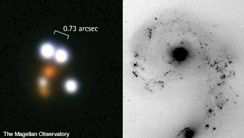 Images from the 6.5 m Magellan telescopes in Chile. (Left) A close-up view of the gravitationally lensed quasar HE0230-2130. The four white objects are unresolved images of the same distant quasar (the tremendously energetic nucleus of a young galaxy). The two reddish objects are foreground galaxies whose gravity bends the quasar’s light to create multiple images. (Right) Much wider view (115 x 100 arcseconds) of the colliding Antennae Galaxies, with uncommonly good 0.27-arcsecond resolution.
Following the machining operation, the surface is ground with a sequence of finer abrasives and gradually brought to the desired shape. The atmosphere sets the accuracy requirements. The wavefront delivered to the telescope is extremely smooth on small spatial scales but has large-scale irregularities increasing to many microns on scales of 8 m or larger. The mirror surface needs to be several times better than the atmosphere on all scales. If it is, the surface errors are insignificant when adaptive optics are not used to correct for the atmosphere, and they are corrected for free when adaptive optics are used.
The use of active optics to control the shape of the primary mirror further relaxes the accuracy requirements on the largest scales, because we can bend in low-order aberrations like astigmatism with small changes in support forces. This relaxation is valuable for the difficult optical test in the lab. One can make wavefront measurements in the telescope by using the telescope’s natural imaging property; these measures do not have to rely on a null corrector, so they’re more accurate on large spatial scales than those made in the lab. Small misalignments in the null corrector would cause large-scale errors in the polished surface, and these can be fixed with active optics once a more accurate wavefront measurement is made in the telescope. Likewise, we can neglect slight mirror support errors and temperature variations in the glass that cause low-order aberrations during lab testing.
Measuring the off-axis segments
So why do we need a 3.75-m mirror to measure a GMT segment? Because the null corrector for the off-axis segments has to do so much more than any null corrector ever built. It has to make the template wavefront, with its 14 mm of aspheric departure, to an accuracy of about 1 µm on large scales and a smoothness of a few nanometers on small scales.
Among traditional, axisymmetric telescopes, the LBT has the most aspheric primary mirrors—each one is a symmetric paraboloid—with 1.4 mm of aspheric departure. Its null corrector consisted of a pair of lenses separated by 67 cm. The GMT null corrector, designed by Burge, is shown in the figure on the facing page. In addition to the 3.75-m mirror, it contains a second smaller mirror and a computer-generated hologram. Oblique reflections off of the two mirrors do most of the shaping of the wavefront, and the CGH cleans up the remaining aberrations.
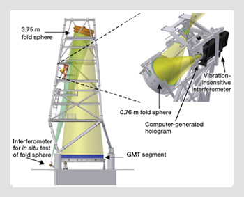 Optical test for the GMT off-axis segments. Model of the principal optical test for the GMT off-axis segments, in the 28-m test tower. At right is a blow-up of the interferometer and first two elements of the null corrector. Gold light cones represent the measurement of the GMT segment, while green cone in the full model at left represents a simultaneous measurement of the large fold sphere.
The most challenging aspect of the GMT null corrector is alignment. The small package containing the interferometer, CGH and smaller mirror requires an alignment accuracy of about 10 µm, and the larger dimensions between that package, the larger mirror and the GMT segment must be controlled to about 100 µm. To get this level of accuracy in a non-axisymmetric system, we rely heavily on holograms and laser trackers. Holograms can be aligned optically to the wavefront (aligned to return a null wavefront to the interferometer), and they provide both optical and mechanical references so that other components can be aligned to the wavefront. We use laser trackers (distance-measuring interferometers coupled with sub-arcsecond angular encoders) to measure the positions and orientations of these reference holograms as well as the mirrors.
For previous mirrors, we could validate the interferometric measurement with a small CGH inverse null corrector. The GMT test wavefront is more than 3 m in diameter by the time it leaves the null corrector—way too large to validate with a CGH. But we can achieve the same goal with an independent measurement of the segment figure, a test that’s sensitive to the low-order aberrations that we would get wrong if there were a misalignment of the null corrector. For this purpose, Burge developed a scanning pentaprism system that scans the surface with a narrow collimated beam, which is focused on a detector in the mirror’s focal plane. The displacement of the focused spot is proportional to the slope error on the surface.
These slope measurements are surprisingly accurate—to about 0.1 arcsecond rms surface slope. That’s because the scanning pentaprism, with two internal reflections, deflects the beam by a constant 90° angle independent of small rotations of the prism. We use a second, fixed pentaprism to compensate for misalignments and instability in other components. A set of four scans at different diameters determines the first eight low-order aberrations to an accuracy of 50 to 100 nm rms, similar to the predicted accuracy of the principal optical test and well within the correction range of active optics.
The principal test and scanning pentaprism test work only on a polished surface. We measure the ground surface by scanning it with a laser tracker. (An infrared version of the principal test is possible but complicated by the use of holograms.) The tracker measures distance and angles, giving the coordinates of each sample point in 3D. It has sub-micron accuracy in its distance measurements, so it gives similar accuracy in the surface measurement if the tracker is located near the mirror’s center of curvature.
The measurement is sensitive to drift in the position of the segment and the laser tracker during the scan, so we monitor fixed references at the edge of the mirror with a standard distance-measuring interferometer and compensate for any motion. There are similar references and an in situ calibration that compensate for errors in the angle measurements. Our goal is sub-micron accuracy in the GMT measurement.
The full set of test optics for the GMT segments has been installed in a new 28-m test tower at the Mirror Lab. The new tower replaced the original 24-m tower, which was used for all mirrors through the LBT primaries but wasn’t quite large and stiff enough to accommodate the GMT tests. The GMT project and Steward Observatory have invested a tremendous effort in developing an accurate, redundant and convenient suite of tests for these segments. Combined with the casting, machining and polishing equipment at the Mirror Lab, these test systems provide a complete manufacturing plant for efficient serial production of the GMT segments.
The optics for the GMT build on successful experience with honeycomb sandwich mirrors in the MMT, Magellan telescopes and LBT. The GMT design combines the smoothness and stability of large honeycomb sandwich segments with low-noise adaptive secondary segments, to provide a dramatic advance in sensitivity and resolution.
This material is based in part on work supported by AURA through the National Science Foundation under Scientific Program Order No. 10, as issued for support of the Giant Segmented Mirror Telescope for the United States Astronomical Community, in accordance with Proposal No. AST-0443999 submitted by AURA.
Buddy Martin is a project scientist in the Steward Observatory Mirror Lab and an associate research professor at the College of Optical Sciences at the University of Arizona, U.S.A.
References and Resources
>> R.N. Wilson, Reflecting Telescope Optics II, Springer, Berlin (1999).
>> M. Johns. “Progress on the GMT,” in Ground-based and Airborne Telescopes II, L.M. Stepp and R. Gilmozzi, eds., SPIE Proc. 7012, paper 70121B (2008).
>> J.I. Lunine et al. “The detection and characterization of exoplanets,” Physics Today, May 2009, p. 46.