
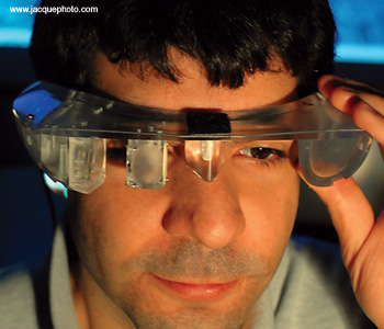
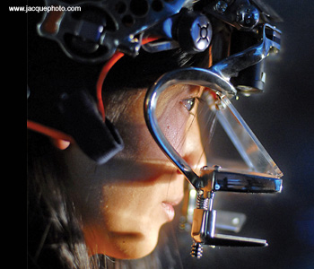
 ODALab’s first prototype free-form eyeglass display (2006).
In today’s world, many people consider their cell phones or PDAs to be extensions of themselves. These devices enhance the way we interact with the world by allowing us to retrieve information and connect with people instantly. Imagine taking that integration further—by wearing your mobile device within a pair of sunglasses. Head-worn displays (HWDs) will make wireless access, video display and 3D visualization more accessible than ever.
The concept of overlaying computer-generated imagery on the real world—known as “augmented reality”—has been under development since the 1960s, and it is poised to revolutionize the way we perceive and interact with digital information. Imagine, for example, the surgical rooms and doctors’ offices of the future, where surgeons, physicians and medical staff are using HWDs to guide an imaging or scalpel device within the human body, or to analyze or monitor a feature of a patient’s physiology in more detail. In remote spaces, hikers will rely on miniature GPS electronics to illustrate a path out of the woods or through the mountains. In times of emergency, where split-second decisions determine vital outcomes, rescuers will be able to ascertain when people are in imminent danger as they approach a scene via an immediate, proximal, wireless link that transfers the victim’s heart rate, galvanic skin conductance, or pupil dilation through their glasses.
The miniaturization of visual displays and the evolution of wearable display technology will enable us to enter worlds of all scales, from nano to giga, as never before imaginable. HWDs are core enabling tools to augmented reality that seek to supplement, rather than replace, the real environment with information and computer-generated simulations. Unlike the precursor technology of “look-at” displays, where you might have a pair of displays perched on your nose but cannot see out into the world, the latest generation of HWDs are ergonomically integrated and provide full access to the live environment.
A brief history of head-worn displays
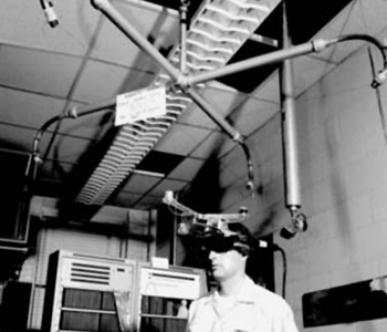 AFIPS Joint Computer Conference Archive (1968).
Researchers have been developing technologies to support interactive 3D visualization for more than three decades. In 1968, leading American computer graphics expert Ivan Sutherland demonstrated the first computer-graphics-driven optical see-through head-mounted eyepiece display at Harvard University. Due to the formidable appearance of the device, it was named the Sword of Damocles (referring to a Greek legend in which a sword dangled over the head of a king).
Within the past two decades, scientists have made great advances in the design of HWDs. In the mid-1990s, a company called Microvision developed retinal scanning displays, which drew a raster display directly onto the retina of the eye. Fisher first proposed head-mounted projection displays for indoor use in 1996. This technology replaces the eyepiece-type optics in a typical HWD with projection optics, which are then combined with a retroreflective screen to enable stereoscopic capability. Over the past decade, the research group in the Optical Diagnostics and Applications Laboratory (ODALab) has been working to miniaturize and develop this technology, as well as designing it for outdoor use.
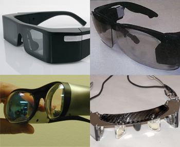 Clockwise from top left: Lumus Light-guide Optical Element, Sony Dual-Holographic Display, ODALab EyeGlass Display and Optical Research Associates.
In the late 1990s, Yamakazi of Canon Japan pioneered free-form prisms for visualization applications. At the same time, Lumus developed waveguided eyewear displays. Sony has recently demonstrated a prototype split-holographic design. Most recently, with the emergence of diamond turning technology, we (Cakmakci and Rolland) have investigated the use of free-form optical surfaces in the design of compact HWDs. In pursuit of a display with market potential, we developed a mathematical framework within lens design for describing free-form optical surfaces and devised a novel lightweight geometry for HWDs.
The photos on the right show some of the prototype designs for see-through HWDs that have been developed by various companies and research groups. These represent the nearest the industry has come to true sunglass displays.
Market barriers
Despite their promise, HWDs have yet to be embraced in the marketplace. In the late 1990s, millions of dollars in venture capital investment flowed into the development of HWDs for the consumer market, without success. One reason that the technology failed was that no viable optical see-through geometry had been identified at that time. A number of opaque HMDs were available, but none of them allowed users to see through to the real world, thus severely limiting the application domain.
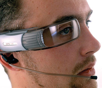 www.Digilens.com
In the late 1990s, the marketing brochure of the now-defunct Retinal Imaging Systems (now Digilens) illustrated what the public wanted—and is still waiting for: a display that looked “cool” and is as comfortable to wear as a pair of sunglasses, even if they are a bit large. While that development, based on writeable holographic display technology, did not succeed, the company has persevered, and their newest product is making headway in this lucrative market space.
Another factor currently limiting the success of HWDs is a lack of bright, compact, full-color sources. However, there have been dramatic recent advances in sources with the emergence of LEDs. Although more work is needed, particularly with packaging and implementation, LEDs are now sufficiently bright to support this industry. This was not the case toward the end of the last decade. In addition, the technology and form factors that make up the microdisplay industry have evolved to the point where they can support small packaging.
However, even though the technology is in place (or nearly so), the economics are not. Currently, the microdisplay industry is far from stable, with no established market leader. Organic LEDs, which could evolve as an ideal display for HWDs, are still not as bright as they could be, and, like other microdisplays, they suffer from the lack of a viable supply chain. Another big challenge is getting the timing right. The time-to-market cycle of 18-24 months can easily exceed the lifetime of any particular display format.
For example, Optical Research Associates recently developed a prototype that took about 18 months from concept to completion. By the time it was finished, the microdisplay that it had been modeled around was no longer available, and the technologies that replaced it were so different that the company was forced to return to the starting point of the process.
Another limitation to the industry is imposed by the demands of style. In order for the HWDs to appear unobtrusive, all of the hardware associated with the display needs to be hidden in the sidebands of the glasses. With that as the goal, the width of a person’s head when he or she is using spherical or aspherical optics sets the cant angle on the optics, which is the angle of the optical combiner to the visual axis. That cant angle has not been accepted by the market from an aesthetic point of view.
This is where optics innovation enters the picture. Lumus, Sony, and others have created a technology that accommodates the width of the head with geometries that are best described as waveguides. These examples represent how the marketplace drives innovation.
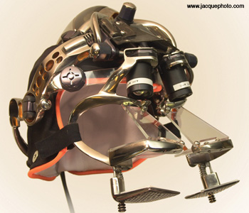 ODALab mobile head-worn projection display (HWPD).
HWPD development
At the same time that ODALab researchers have been working to perfect see-through augmented-reality displays, they have been further developing head-worn projection displays (HWPDs), which use projection optics in combination with a retroreflective screen to enable stereoscopic capability.
Over the past decade, investigators have worked towards miniaturizing the technology behind HWPDs and designing lightweight optics to enable a large field of view. In 1998, researchers at ODALab designed projection optics weighing 8 g per eye for a 1.35-in. diagonal back-lit LCD microdisplay. In 2004, they achieved 6-g-per-eye optics for a 0.6-in. diagonal OLED format.
Next, in collaboration with NVIS Corporation, researchers developed an HWPD based on a liquid crystal reflective microdisplay and the required polarization optics that accompany it. Such a display presented improved brightness compared to the OLED microdisplays of the time. However, this came at the expense of compactness. In 2005, NVIS presented its first prototype at the Image Society Conference in Scottsdale, Ariz., U.S.A., and at the Interservice/ Industry Training, Simulation and Education exhibit (I/ITSEC) in Orlando, Fla., U.S.A.
In designing ultra-compact optics of a few grams per eye for HWPDs, we have found that diffractive optical elements (DOEs) may be used in place of doublets for the correction of chromatic aberrations, given the strong negative chromatic dispersion of DOEs. A trade-off in the use of DOEs in optical system design is a small loss in diffraction efficiency that can affect the contrast of images. To assess performance, we must thus quantify the DOE efficiency across the visible spectrum to ensure that the contrast and color rendition will be acceptable. Particularly useful is the integrated diffraction efficiency metric, which was proposed by Buralli and Morris in the form of a single number that multiplies the MTF curves to account for the drop in the polychromatic MTF when one uses DOEs.
Recent work in HWPD technology has focused on reducing the size of the cells in the retroreflective materials. Previous research has been restricted to retroreflective material of cell sizes on the order of 100 µm, which is what is currently available on the market. This large cell size has prevented the development of a mobile display. Moreover, earlier HWPD architecture requires that the retroreflective material be mounted, typically on a wall in a room by design. One of the most lightweight wall-mounted displays developed in the ODALab was recently tested in a clinical setting for the visualization of tumors in 3D models of lungs for radiotherapy planning.
More recently, ODALab has been working with a leader in holographic embossing to make a new retroreflective material that will have smaller cells. The smaller cell size will allow for the creation of a viable, self-contained HWPD. This unit would put the retroreflective material just a few inches from the eyes. In other words, it would be mounted directly on the HWPD, making for a fully mobile see-through unit. Clearly, a path is emerging to a viable consumer unit.
Video goggles and other advances
Another technical path that researchers and companies are pursuing is that of immersive video goggles or glasses. For example, the company MyVu offers sleek “digital eyewear” that users can plug into their iPod or personal video device to create a big-screen experience. The frames also leave enough room to allow people to view the real environment. Ultimately, however, the goal for researchers is to create augmented displays that can superimpose images and information on the real world. Experience with prototype units has shown that there is a nearly ideal field of view for an augmented display at 15-25 degrees.
Among the HWD community, it is widely believed that the physical obtrusiveness of the designs developed to date are the major factor preventing consumer acceptance, for both horizontal and vertical markets. But the surge in consumer interest in cell-phone-based video suggests a readiness for people to adopt small, comfortable, low-cost wearable augmented-information displays.
So far, there have been a number of inspiring optical design ideas, including the early work of Bettinger and Spitzer, and Yamazaki’s free-form design. (For a more comprehensive review, see Cakmakci and Rolland [J. Display Technol. 2, 199-216]). Some other recent advances include spectacle-mounted telescopic systems developed for individuals with visual impairments and Eli Peli’s wide-field Keplerian telescope, which is built within the spectacle lens. The latter design uses embedded mirrors inside the carrier lens to fold the optical path and powered elements for higher magnification. The integration of the optics enables the wearer to simultaneously view the magnified and unmagnified field within the eyeglass format.
At ODALab, we are now building what we believe will become an embedded technology in everyday life: eyeglass displays that operate as a small, lightweight computer monitor. This work combines research in optics and optical design with industrial and mechanical design. We are using our expertise in designing off-axis combiners, free-form optics, and plastic and diffractive optical lenses to develop extremely compact optical designs.
Ultimately, however, the user plays the most critical role in our design process. The team is gathering sensory input (such as visual perception) from eyewear users in order to achieve ergonomically and perceptually viable high-performance systems. We believe, along with many others in the field, that eyeglass displays will dominate as the visual hardware platform for future visual user interfaces.
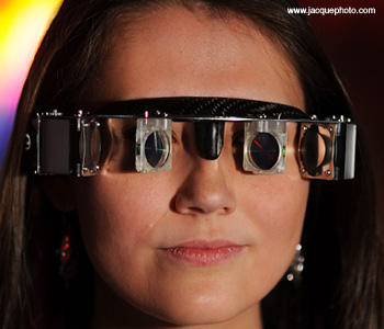 ODALab stereoscopic free-form eyeglass display (2008).
Image-generation technology is critical to the development of eyeglass displays. While laser-based retinal displays have been developed as a niche technology for more than 20 years, microdisplays continue to dominate the market. To date, microdisplays typically only display about one-quarter of a million pixels (i.e., VGA format with 640 x 480 corresponds to 307,200 pixels or 0.3 mega-pixels) and vary in size from about a quarter-inch to a half-inch. However, 1,920 x 1,024 displays are on the horizon.
Mature microdisplays typically provide roughly 1 million pixels and are about 1 in. in size. The format we are seeking requires microdisplay sizes of a quarter or a third of an inch in order for the optics to fit within the eyeglass form factor. Optical system designs that magnify these small microdisplays within the most compact volumes have remained a challenge in delivering head-worn display solutions that can be targeted widely across a range of applications.
Free-form optics
ODALab is in the midst of a paradigm shift toward the use of free-form optics for the optical design of compact and lightweight eyeglass displays. Free-form optics are optical surfaces without rotational symmetry. These design forms are in an intermediate stage of development and are proving to be more interesting than expected. For the augmented display of information, we have found a 25-degree field to be nearly optimal for image quality and form factor combined.
ODALab has recently completed a catadioptric prototype system composed of a single mirror and single lens. The dual-element design uses in its original first design an x-y polynomial to describe the surface of the free-form mirror. The mirror is tilted at about 30 degrees in order to provide the necessary mechanical clearances around a human head. In this first prototype, there is no see-through mode for this portion of the field. Interestingly, even though the center of the view space is fully blocked (because of the opaque mirror) for both eyes, the brain easily adapts to merge with this loss of information using the fully unblocked peripheral vision. The next generation of eyeglass displays will offer see-through capability using free-form optics.
In seeking the optimal surface for the free-form mirror, designed with maximal eye box size, field of view and image quality, we have proposed using radial basis functions (RBF) as a means of describing the free-form optical surfaces and comparing their performance to multivariate polynomials using the MTF criteria. One of the benefits of using the RBF approach is that, in the case where the number of basis functions is equal to the number of data sites, we are guaranteed an invertible interpolation matrix with the RBF approach.
A second advantage is that any aperture shape can be accommodated without any modifications (Gram-Schmidt or otherwise) to the framework. This is because basis functions can be shifted to any set of distinct data sites, regardless of the shape of the curve (i.e., aperture) containing the sites. In addition, the framework remains unchanged going from 1D to 2D or higher dimensions. A final benefit is the potential connection between the surface representation and the fabrication point influence functions.
How do free-form optics help solve some of the challenges of developing see-through, compact, lightweight, low-cost, robust and manufacturable HWDs? Free-form surfaces can represent local shape changes over independent subapertures across the surface but with features that only apply within the subapertures. For a surface with many subaperture zones, the features can evolve dramatically as one travels across the extent of the surface.
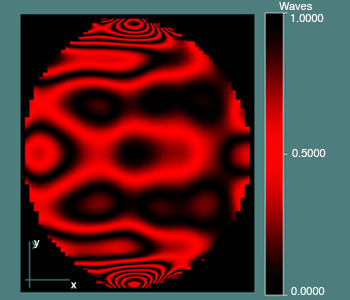 ODALab free-form surface departure from Zernike surface.
Conceptually, we think of free-form surfaces as those that confer the ability to show the top of a surface as different from the bottom, or, similarly, the left side as different from the right as shown in the figure on the right. On the other hand, rotationally symmetric aspheres are generated by revolving a 1D base curve around an axis. From the point of view of surface description, the symmetry along the rotation axis is a limitation in the design of eyeglass displays.
The stereo eyeglass display prototype has a 640 x 480 VGA resolution (1.5 arcminutes in visual space), an 8-mm eye box, 15-mm eye clearance, 20-degree diagonal full field of view and two plastic optical elements. It is predicted to have a 20-percent MTF at the Nyquist frequency evaluated over a 8-mm eye box, less than 4 percent distortion, and a total system weight of 124 g, including the weight of the optics, electronics, microdisplay and the opto-mechanical frame. The design came from using an off-axis configuration combined with the new type of free-form optical surface shape, as opposed to a rotationally symmetric aspheric design, as previously attempted by several optical designers.
A single free-form mirror would be an ideal solution for a compact eyeglass display. The tilts of the free-form mirror are determined by the microdisplay placement requirements. Therefore, the tilts of the free-form mirror are a constrained degree of freedom. In order to ensure comfortable viewing, we also need to ensure sufficient eye clearance (≥ 15mm). The major variable in the case of a single mirror magnifier is the surface shape.
We find the potential use of free-form optics for eyeglass displays very promising. Just when it seems that everything has already been invented in optical system design, a new paradigm is realized. With these and other exciting developments being made in the area of head-worn displays, the future is so bright you have to wear glasses.
Jannick Rolland is an OSA Fellow and a professor of optics and biomedical engineering at the University of Rochester. She is also the director of the Optical Diagnostics and Applications Lab. Ozan Cakmakci, a former Ph.D. student of the ODALab, is now an optical engineer with Optical Research Associates.
References and Resources
>> The Optical Diagnostics and Applications Laboratory at the University of Rochester with partner labs at the University of Central Florida and Armstrong Atlantic University.
>> I.E. Sutherland. “A head-mounted three-dimensional display,” in AFIPS Proc. Fall Joint Computer Conf. 33, 757–64 (1968).
>> D.A. Buralli and G. M. Morris. “Effects of diffraction efficiency on the modulation transfer function of diffractive lenses,” Appl. Opt. 31, 4389-96 (1992).
>> T. Furness. “Virtual Retinal Display,” U.S. Patent 5,467,104 (1995).
>> R. Fisher. “Head-mounted projection display system featuring beam splitter and method of making same,” U.S. Patent 5,572,229 (1996).
>> S. Feiner. “The importance of being mobile: Some social consequences of wearable augmented reality systems,” in Proc. IWAR ‘99 (IEEE and ACM Int. Workshop on Augmented Reality) San Francisco, Calif., U.S.A. 145-8, October 20-21, 1999.
>> S. Yamazaki et al. “Thin wide-field-of-view HMD with free-form-surface prism and applications,” in Stereoscopic Displays and Virtual Reality Systems VI, 3639, SPIE, San Jose, Calif., U.S.A., 453-62, 1999.
>> H. Hua et al. “Design of an ultra-light and compact projection lens,” Appl. Opt. 42(1), 97-107 (2003).
>> A. Yaakov. “Substrate-guided optical beam expander,” Patent U.S. 6,829,095 (2003).
>> Y. Ha and J.P. Rolland. “Compact lens assembly for the teleportal augmented reality system,” U.S. Patent: 6,804,066 B1 (2004).
>> J.P. Rolland et al. “Albertian Errors in Head-Mounted Displays: Choice of Eyepoints Location for a Near or far Field Task Visualization,” J. Opt. Soc. Am. A 21(6), 901-12 (2004).
>> J.P. Rolland et al. “Development of Head-Mounted Projection Displays for Distributed, Collaborative Augmented Reality Applications,” Presence: SI Immersive Projection Technology 14(5), 528-49 (2005).
>> J.P. Rolland and H. Hua. “Head-mounted displays,” in Encyclopedia of Optical Engineering, R.B. Johnson and R.G. Driggers, eds., Taylor and Francis (2005).
>> O. Cakmakci and J.P. Rolland. “Head-Worn Displays: A Review,” J. Display Technol. 2, 199-216 (2006).
>> O. Cakmakci and J.P. Rolland. “Design and Fabrication of a Dual-Element Off-Axis Near-Eye Optical Magnifier,” Opt. Lett. 32(11), 1363-5 (2007).
>> R. Martins et al. “A mobile head-worn projection display,” Opt. Express 15, 14530-8 (2007).
>> O. Cakmakci et al. “Application of Radial Basis Functions to Shape Description in a Dual-Element Off-Axis Magnifier,” Opt. Lett. 33(11), 1237-9 (2008).
>> O. Cakmakci et al. “Optimal local shape description for rotationally non-symmetric optical surface design and analysis,” Opt. Express 16, 1583-9 (2008).
>> O. Cakmakci et al. “Application of Radial Basis Functions to Shape Description in a Dual-Element Off-Axis Eyewear Display: Field of View Limit,” Journal of the Society of Information Display 16(11), 1089-98 (2008).
>> H. Mukawa et al. “A full color eyewear display using holographic planar waveguides,” In Proceedings of the Society for Information Displays 3901, 89-92 (2008).
>> E. Peli and F. Vargas-Martin. “In-the-spectacle-lens telescopic device,” J. Biomed. Opt. 13(3), 034027 (2008).
>> A.P. Santhanam et al. “A Display Framework for Visualizing Real-time 3D Lung Tumor Radiotherapy,” J. Display Technol., Special Issue on Medical Displays (2008).