
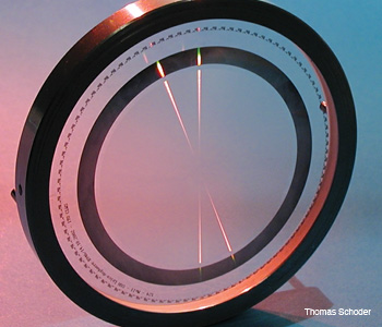
 A computer-generated hologram is used as a phase-transmission diffractive null corrector for testing aspheric optics.
Aspheric lenses have become synonymous with high-performance optics. In fact, many lens vendors have made their aspheric elements a prominent part of their advertising campaigns. Aspheres are increasingly being used in optical systems for all kinds of applications, with varying degrees of asphericities (deviations from a best-fit sphere) and accuracy requirements.
These surfaces can be powerful tools for reducing the number of elements in a lens (and with it the size and weight), thereby enhancing system performance. If a surface is allowed to deviate from spherical designs, additional aberrations can be corrected as well. However, these advantages come with major drawbacks in fabrication and assembly.
Nevertheless, modern optical systems, ranging from those used in daily applications to the ones in high-end technological systems, depend more and more on the use of aspheric surfaces, making the cost-effective production of aspheres a subject of central importance to the optics industry.
In recent years, the production of these elements has seen an overwhelming increase, in part due to the development of new fabrication technologies such as computer-controlled polishing, magnetorheological finishing and ion beam figuring. These techniques allow the deterministic polishing of precise surfaces in less time than was previously possible.
As the fabrication of extremely accurate surfaces has proliferated, so too has the demand for high-precision measurement. After all, one cannot produce surfaces better than it is possible to measure.
The measurement of aspheres in the production process is of essential importance for achieving the final desired surface. Since the production sequence is iterative, several steps must be taken between surface shaping and measurement before the required accuracy level is achieved.
Up until now, the lack of an effective measurement system has prevented a reduction in the production costs of aspheric elements. The source of problems for the testing of aspheres is the same thing that makes these surfaces so attractive to optical designers: their individual shape. The challenge is to find an effective measurement system that provides the flexibility for engineers to cope with a wide range of asphericities while maintaining the required degree of accuracy.
Testing of aspheric surfaces
Before one can understand the complexities of aspheric testing, it may be helpful to review the interferometric testing of standard spherical surfaces, which is simplified due to their intrinsic symmetry.
The only free parameter of a sphere is its radius. A spherical wavefront generated by, for example, a transmission sphere is enough to test a whole range of spheres. Putting the center of curvature of the test part coincident with the focus position of the transmission sphere, the test wave of the interferometer makes a normal incidence angle with the surface under test and is retroreflected.
This test configuration, commonly known as a null test, shows the deviations of the measured surface from the reference sphere.
If we try to test an aspheric surface with such a standard interferometer, not only will the fabrication errors be measured but also the deviation of the asphere from the test spherical wave produced by the interferometer. Depending on how big this deviation is, the number of fringes in the interferogram will increase until its evaluation is no longer possible due to subsampling.
Typical asphericities range from 10 µm to more than 1,000 µm, and the deviation of the asphere from its design form is usually required with accuracies better than λ/10, or, in the case of lithography systems, on the scale of nanometers. This huge ratio between measurement accuracy and dynamic range shows the difficulties associated with characterizing these elements.
Testing conic section type aspheres
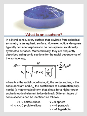
Aspheres frequently are described as conic sections. (See the box above, “What is an asphere?”) Purely conic sections—i.e., those defined only by the conic constant, without correction polynomial—are so-called stigmatic surfaces. The name stigmatic is due to their unique imaging properties: When used as a mirror, these surfaces image a point source to a perfect focus.
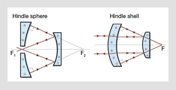 Interferometric testing of conic sections. (Left) Test of a concave hyperboloidal surface with a Hindle sphere. (Right) Convex paraboloid tested with a Hindle shell.
This property is exploited in optic design, but it can also be used to design relatively simple test setups. For conic-section surfaces of revolution like paraboloids, hyperboloids and ellipsoids, several tests are available. These test arrangements usually make use of spherical auxiliary components such as a Hindle sphere for hyperboloids or the Hindle shell for convex paraboloids and ellipsoids.
Although these tests have been of the utmost importance for developing mirror systems, such as those used for astronomy applications, they cannot provide a complete solution to today’s problem of aspheric testing, since pure conic sections constitute a minority of surfaces. In the general case for non-conic sections, these simple test configurations fail to provide a proper measurement arrangement.
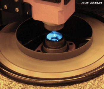 Direct laser writing system CLWS300. The polar coordinate system can write diffractive elements on substrates with a diameter of up to 300 mm and 20 mm in thickness.
Null correctors
The standard way to deal with a general asphere is to introduce some sort of correction optics in order to adapt the incoming test wavefront to the surface under test. This null optic (or null compensator or null corrector) generates from the incoming spherical wave a wavefront that impinges normally to the test surface and is thus retroreflected, forming a null interferogram.
As in the case of testing spheres, the resulting interferogram shows the deviations of the surface from the design prescription if the null optic is perfect. The accuracy of the method is clearly dependent on how well the null compensator is fabricated. The fact that each type of asphere requires its own custom-made null corrector is largely what makes asphere testing and generation so expensive and time-consuming.
Null correctors may be implemented with refractive, reflective or diffractive optics. Refractive compensators are optical systems designed to generate the appropriate aspheric test wavefront for the test surface. The fabrication of these systems is extremely expensive and time-consuming, and the certification of the compensators is challenging.
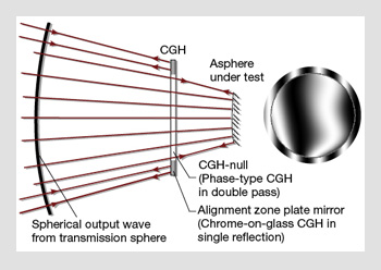 Diffractive null optics with peripheral alignment structures. (Left) The alignment ring is a diffractive mirror that retroreflects the spherical wave coming from the transmission sphere when the CGH is placed in the correct position. (Right) Simulated interferogram showing some misalignment (external ring-shaped interferogram).
The most commonly used way to implement null correctors is diffractive—by means of computer-generated holograms (CGHs). A CGH is a diffractive element that uses grating-like structures with lateral feature sizes down to a few micrometers and heights of a few hundred nanometers. A CGH can be considered as a hologram that reconstructs the desired aspheric wavefront when illuminated correctly.
The difference between a CGH and a conventional hologram is that the recorded object does not need to exist physically. The recorded object is a perfect asphere that may exist only in the computer. From the perfect asphere shape and the known illumination, it is possible to directly calculate the microscopic grating structures of the hologram and produce it by means of high-resolution printers. In practice, engineers typically use high-precision lithography equipment, such as laser-writing systems or electron-beam writers.
In fact, diffractive null correctors have, in practice, almost entirely replaced the costly and time-consuming fabrication of refractive compensators.
Diffractive null correctors: computer-generated holograms
The accuracy of CGHs is defined by the lateral positioning accuracy of the lithographic equipment. A distortion of the pattern of the CGH results in a phase error of the reconstructed wavefront that is proportional to the local line density of the CGH and the amount of the CGH pattern error:
WPD = –mRλ0ζNνN
(PD=Wavefront aberrration caused by hologram pattern distortion, R=Diffraction order, λ=Wavelength, ζ=CGH pattern error, ν=Spatial frequency)
Positioning accuracies of 50 nm and better over the whole surface of the element are state-of-the-art. The dimensions of the CGH are dependent on the geometry and size of the surface we desire to test; common CGH sizes range from tens to hundreds of millimeters.
The fabrication of such elements can take anywhere from a couple of hours to several days, depending on the writing system. One of the advantages of diffractive null correctors over conventional refractive or reflective null optics is the broad range of asphericities that can be covered. The amount of asphericity has only a minor influence on the accuracy of the reconstructed wavefront.
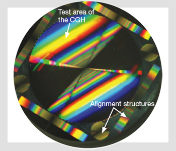 Diffractive reflection element with alignment elements on its periphery.
An additional advantage is the possibility of implementing alignment structures that help to control the position of the null element with respect to the interferometer and the asphere. This reduces alignment errors that could otherwise be misinterpreted as surface-figure errors. The alignment structures are written in the same instance as the null element and have virtually no decentering error.
The figure on the right shows a diffractive mirror implemented as a binary-phase CGH. The central area is used for the testing of an aspheric system, while all the additional external structures (cylindrical and Fresnel lenses) are used for alignment purposes.
One of the disadvantages of diffractive elements is the generation of unwanted diffraction orders and spurious light.
A widely used technique to ease the filtering out of stray light is to add a wedge to the hologram phase function. This generates a carrier frequency on the hologram pattern that helps to separate spatially the unwanted orders from the desired design wavefront.
Then, by means of an appropriate aperture, we can filter out these spurious orders and select the correct one. Although modern fabrication equipment shows an excellent and ever-improving writing accuracy—which has been pushed by the requirements of the semiconductor, aerospace and other industries—the need to catch the residual uncertainties still remains; for high-precision measurements with accuracies in the range of nanometers, the measurement setup as well as the CGH must be calibrated.
Calibration of the null correction optics
The calibration of aspheric null optics is a critical issue, since the null optic ultimately defines the reference shape of the asphere. Calibration can be done against an existing reference. An absolute calibration procedure does not require such a reference, but calibrates against a mathematically perfect shape. Absolute calibration procedures exist for special surfaces with high symmetry, such as planar or spherical surfaces.
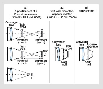
Absolute calibration procedure for an aspheric null test with a diffractive master element. Step (a): Calibration of the diffractive master element. Twin-CGH used as a zone plate. Step (b): Calibration of the aspheric null setup. Twin-CGH used as diffractive aspheric master (null mode). Step (c): Testing of the asphere with the calibrated test setup.
However, for the general case of an aspheric surface, there are no established methods for measuring the complete generated aspheric wavefront with the required accuracy and lateral resolution. In the case of rotationally symmetric surfaces, the symmetry can be used to separate the rotationally and non-rotationally symmetric parts of the surface error.
Within recent years, researchers have proposed and demonstrated absolute calibration methods based on CGH. With a computer-generated hologram, it is possible to produce, simultaneously, several different wavefronts. This approach allows for the generation of auxiliary wavefronts that can be measured with standard test procedures. The results of these measurements are the errors intrinsic to this CGH—i.e., error due to the pattern distortion of the diffractive structures and error due to the substrate (surface figure error, glass inhomogeneity).
From these errors, the absolute errors of the aspheric wavefront can be deduced. As we mentioned before, the pattern distortion error is proportional to the local spatial frequency of the diffractive structures and can thus be easily recalculated for the design function of the aspheric wave. To this, the substrate error is added, corrected for the slightly changed path of the test wave through the substrate.
The figure above shows the necessary elements and measurements for calibrating an aspheric setup using a diffractive calibration element that replaces the surface under test. This diffractive calibration element (twin-CGH) is, on one hand, the holographic analogue to the asphere that it replaces, and, on the other, the hologram of a spherical mirror (a Fresnel zone plate). With the five-position test for Fresnel zone plates depicted on the left of the figure, the diffractive calibration element can be characterized and then used to in turn calibrate the test setup before the aspheric surface is measured.
Flexible measurement techniques
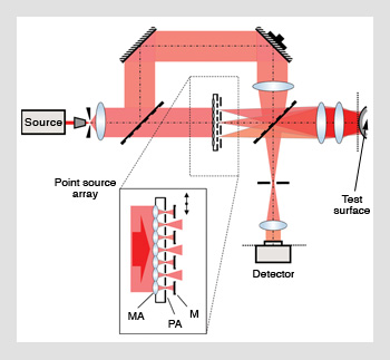 Interferometer with multiple test beams. A point source array generates several tilted wavefronts that reach the test surface under different angles. MA=microlens array; PA=point source array; M=source selection mask.
The increasing availability of CGH has made diffractive null optics an economic alternative to refractive and reflective null optics. Nevertheless, testing with individual null optics is not an economic solution for the production of small-series or prototype aspheres. Also, the production times (design and fabrication itself) for the null corrector might become prohibitive. Current research efforts are oriented toward developing alternative techniques for the rapid, flexible and precise characterization of aspheric surfaces.
In the past few years, several approaches for aspheric testing have reached the market. The ones that have made the most impact are stitching-based configurations and a so-called absolute method, where the asphere under test is scanned using a distance-measurement principle.
One of the main disadvantages of these methods is that they require many mechanical displacements of the test part. Therefore, these measurement systems split up the metrology task into a series of subsequent measurements that, after they have been acquired, are put together to yield the complete measurement.
The mechanical displacement slows down the measurement process and requires a somewhat bulky multi-axis positioning system. This might represent a problem for the integration of such measurement systems into an automated production chain of aspherical elements.
Recently, researchers have proposed an approach that targets the boundary condition of process-integrated aspheric testing (see Liesener and Garbusi et al.). It avoids all mechanical movements of the surface under test, but works instead with a non-standard illumination. As opposed to a standard interferometer, where only one wavefront impinges onto the surface under test, this new type of interferometer uses many wavefronts simultaneously; they are generated using an array of coherent point sources.
 Test regions on this steep asphere (with an aspheric departure of 800 µm) are generated by the multiple test beams and are eval-uated in parallel.
This strategy allows for the parallel measurement of aspheric surfaces in a very short time, even for strong aspheres with deviations from the best-fit sphere of several hundred microns. Each source generates a defined test area on the surface of the test element where no subsampling or vignetting takes place. The system is designed such that the measurement areas generated by the whole source array cover the whole surface of the asphere.
Leaving the null-test configuration enables a wide dynamic range in the asphericities to be measured but also implies that the interferometer must be fully characterized in order to separate the phase contributions of the interferometer itself and the wavefront being measured. Thus, special calibration and measurement procedures were developed to cope with the effects of the so-called retrace aberrations introduced by the non-null test configuration.
The interferometer is designed to achieve an accuracy of λ/30 with sag deviations from the best-fit asphere of up to 1,000 µm; it has shown a measurement time of less than 40s. Although the system has been developed for the testing of aspheres, it is capable of measuring mild free-form surfaces with deviations of the surface normals from the best-fit sphere of up to 5°.
Final remarks
There is no optimal solution for aspheric testing that will fit every optical engineer’s needs. However, researchers are now developing viable alternatives to the static null compensator. Some of these methods are even primed to tackle the next challenge for high-precision metrology—testing freeform surfaces without any symmetry, such as those used for heads-up displays or more complex and unique optical systems.
The authors greatly appreciate the funding of part of this work under German Government grants BMBF FKZ 13N7861 and FKZ 13N8742.
[Christof Pruss, Eugenio Garbusi and Wolfgang Osten are with the Institute of Applied Optics, University of Stuttgart, Germany.]
References and Resources
>> M. Beyerlein et al. “Dual-wave-front computer-generated holograms for quasi-absolute testing of aspherics,” Appl. Opt. 41, 2440–7 (2002).
>> P. Murphy et al. “Stitching interferometry: a flexible solution for surface metrology,” Opt. Photon. News 14(3), 38 (May 2003).
>> S. Reichelt et al. “Absolute interferometric test of aspheres by use of twin computer-generated holograms,” Appl. Opt. 42, 4468–79 (2003).
>> C. Pruss et al. “Computer-generated holograms in interferometric testing,” Opt. Eng. 43, 2534 (2004).
>> P. Murphy et al. “Measurement of mild aspheric surfaces with subaperture stitching interferometry,” Proc. SPIE TD03, 73-5 (2005).
>> J. Liesener. “Zum Einsatz räumlicher Lichtmodulatoren in der interferometrischen Wellenfrontmesstechnik,” Dissertation, Universität Stuttgart (2006).
>> E. Garbusi et al. “New technique for flexible and rapid measurement of precision aspheres,” Proc. SPIE 6616, 661629 (2007).
>> R. Hentschel et al. “Advanced Optics Using Aspherical Elements,” SPIE Press, Vol. PM173 (2008).
>> M.F. Kuechel. U.S. Patent Nos. 6,781,700, 6,972,849 and 6,879,402.