
 Photorealistic image looking into a circle-to-oval coupler that has an RGGB LED array.
The output of light emitting diodes (LEDs) has improved dramatically over the past 15 years. In fact, LEDs have the potential to replace most conventional light sources within the next 15 years. The trend started when InGaN technology provided a 400 x boost in the output of blue LEDs compared to silicon carbide technology. These blue LEDs were combined with a YAG phosphor to create a stable, efficient white light source, causing lighting companies to ponder the future of their basic lamp technologies.
The efficacy of white LEDs—defined as lumens out divided by wall plug watts in—has already surpassed that of incandescent technology and is now about the same as fluorescent lamp technology. These improvements in efficacy have become especially important in light of global concerns over fossil-fuel consumption. Australia has recently announced that it will introduce new energy efficiency standards, which will likely result in a ban on the sale of incandescent light bulbs. Similar plans have been proposed in Ontario, Canada, and several U.S. states, including California and New Jersey. Although compact fluorescent bulbs are expected to replace most incandescent lamps over the near term, LEDs could become the light source in the future.
Historically, LEDs were primarily used as low-power monochromatic indicator lamps. One of the most common LED packages was the T 1-3/4 thru-hole package (above left). The 1-3/4 designates the package diameter in eighths of an inch, so the lens has an outside diameter of roughly 5 mm. The die that emits light was only 0.3 x 0.3 mm and was nominally used with a maximum current of 20 milliamp. Larger sizes and higher currents were not typically used because the T 1-3/4 package used leads that were not able to handle the higher thermal load.
To provide more light, the size of the light emitting die was increased, with a 1 x 1 mm die becoming a fairly common size. These larger die use higher currents (e.g., >350 mA), and that has required changes to the thermal design of both the die and the LED package. Some packages can handle currents greater than 1 A for a 1 x 1 mm die. The increase in the die size and the increase in LED efficiency have both contributed to the improvement in LED package output.
LED packages can now provide hundreds of lumens compared to one or two. Of course, multiple die can be combined to produce even higher output. For example, researchers at Lamina demonstrated a 28,000-lumen solid-state white light engine.
Brightness vs. luminance
The term “high-brightness” LED has been used to describe LEDs that have a sufficiently high luminance that viewers can’t look directly at them. While luminance is a precise technical term that defines a quantity that can be measured, brightness is a non-quantitative reference to physiological sensations and perceptions of light.
 Optical illusion: brightness vs. luminance. While luminance is a precise technical term that defines a quantity that can be measured, brightness is a non-quantitative reference to physiological sensations and perceptions of light. The constant-luminance central rectangle appears to have a gradient in “brightness” when the background is non-uniform (top). However, then the background and central rectangle are separated, the brightness of the central strip no longer appears to vary (bottom).
The optical illusion shown in the figure on the right is an interesting illustration of the relationship between brightness and luminance. The light from the thin rectangular strip in the center has a constant luminance, while the background has a luminance gradient. When placed on top of the background, the thin strip also appears to have a gradient in “brightness”—but that is only an illusion. As the lower portion of the figure shows, when the central and background regions are separated, it becomes obvious that the thin strip has a uniform luminance. High brightness tends to imply high luminance, but brightness is less precise and can be used in a more general manner.
The luminance of a light source can be the key factor in determining whether it is possible to deliver sufficient flux for an application. Luminance is the flux divided by the integral of the area and projected solid angle, where the integral of the area and projected solid angle is called the etendue. The portion of an optical system that limits the etendue can occur inside an optical system, such as the size of a spatial light modulator combined with the numerical aperture of a projection lens.
Sometimes the limiting aperture is simply the output size of the optical system. While multiple LEDs can be combined to provide a required number of lumens, adding more LEDs does not increase the luminance of the combined source. In projection systems and automotive headlamps, the luminance of LEDs is not always sufficient. For example, headlamps nominally require more than 25 mega-nits, compared to the 5 to 15 mega-nits that is the state of the art for many white LEDs. (One mega-nit is 1 million candelas per square meter.)
The need for higher luminance has helped to propel the development of some LED sources, such as the photonic lattice technology developed by Luminous Devices. The luminance also increases if the LED size and radiation pattern remain constant and the efficiency increases. Since increases in efficiency are generally correlated with a reduction in cost per lumen, LED technology is expected to push into more high luminance applications as the technology matures.
LED color
High-brightness LEDs can provide colors across the visible spectrum. Both AlInGaP and InGaN material systems are used to produce high-brightness LEDs. Aluminum, indium, gallium and phosphide compounds are used to produce red, orange, yellow and even green colors, while indium and gallium-nitride compounds are used for ultraviolet, blue, blue-green and true-green colors.
LEDs are also used to create white light. This is typically done by using an LED with a phosphor or by combining multiple monochromatic LEDs. The phosphor approach provides a robust integrated package with reasonable efficiency. The use of the phosphor introduces a light loss because of the Stokes shift, so that higher efficiency can be achieved by combining multiple LEDs.
Combining multiple monochromatic LEDs provides the option of tuning the color. For example, a single fixture could provide either a “warm” white or a “cool” white. This tunability is a double-edged sword. The output of the individual LEDs must be adjusted in the correct proportion and mixed throughout the beam pattern. This color control is not only a challenge for high-brightness LED systems, but also for the conventional CIE standards used to characterize lighting systems. Even a couple of percent change in the output of the red LED in an RGB system can produce observable color changes. These tight sensitivities can be controlled using feedback systems that monitor the LED output.
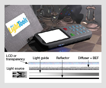 Schematic of a typical backlight design. Rendering of a lit cell phone. The display itself is lit using white LEDs. The keypad and indicator buttons are lit using monochromatic LEDs.
Other benefits of LEDs
In addition to various colors and high output, high-brightness LEDs can provide the long life that is normally associated with semiconductor devices. LED lifetimes can be greater than 100,000 hours—which is significantly longer than the 2,000 hours that is nominally associated with incandescent light bulbs. The long life of LEDs offers a paradigm shift for lighting applications. Rather than designing fixtures where the bulb is replaced periodically, LED lights can outlast the life of the fixture. The new paradigm would be to replace the whole fixture instead of just the light source.
The efficacy of LEDs can be greater than 100 lumens per watt (LPW), and it continues to increase. In the future, efficacies of greater than 200 LPW are possible, with many technology roadmaps expecting more than 160 LPW by 2015. This is impressive compared to tungsten-halogen technology, which provides 15 to 25 LPW, and fluorescent technology, which provides 60 to 100 LPW.
The life, color and amount of light generated by a high-brightness LED is sensitive to the temperature of the semiconductor junction. As the current density in the LED is increased to produce more light, the amount of heat that must be removed to control the junction temperature also rises. This heat is primarily removed through conduction, which is a significant change compared to conventional lighting technologies that rely primarily on radiative cooling.
These thermal considerations are especially important for lighting applications that require a lot of flux, since LED efficacy drops at the upper limit of the allowed junction temperature. The output of commercial products continues to increase as the engineering improves to allow product performance to approach the output demonstrated by research results. Even today, however, high-flux LEDs have been integrated into products that have efficacies of 25 to 50 LPW.
Applications of high-brightness LEDs
With the increase in LED output, LEDs have already replaced other light source technologies in many applications, including traffic lights, automotive signal lamps, mobile phones and flashlights. Work is under way to develop applications of high-brightness sources for projector systems, backlighting technologies, portable lighting, solid-state lighting and regulated illumination.
Projectors
High-luminance sources have been used with spatial light modulators (SLMs) to create projector systems. In recent years, high-pressure discharge lamps, especially high-pressure mercury lamps, have been developed; screen lumens in the range of 500 to 2,000 lumens are common. The SLM technologies used for projectors are usually based on liquid crystals (e.g., transmissive or reflective LCDs) or arrays of movable micromirrors (e.g., DLP). High-luminance sources are desired to minimize the size and cost of the projection system, especially the SLM itself.
With the increase in luminance and total output of LEDs, it is now possible to develop projector systems using LEDs. Many companies are interested in developing a class of projectors that delivers 25 to 50 lumens. Because these projectors are small, they are sometimes called pocket projectors.
One of the benefits of LED display systems is a wider color range than is available with other source technologies. Projector systems can also be used to create rear-projection TV systems. In this case, the SLM is reimaged onto a transmissive screen, and the screen controls the range of angles over which the image can be seen.
Backlighting
There are an estimated 2 billion cell phones in the world today. Many cell phone displays use a backlight system to illuminate an LCD. The most common cell phone backlight system uses LEDs coupled into one edge of a thin plastic light guide, as shown in the diagram below. The light guide contains extractor features that uniformly spread the light over a large area and couple it toward the LCD.
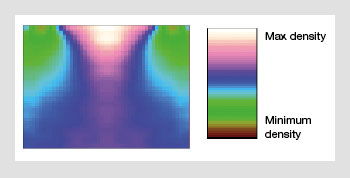 Extractor density for a two LED backlight. The extractor density is lower near the LEDs and varies across the light guide to achieve the desired uniform output.
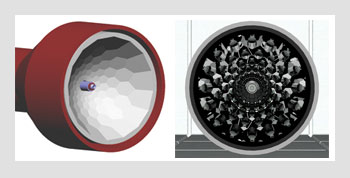 LED flashlight. (Left) CAD isometric rendering of the front of the flashlight that uses a faceted reflector and a side-emitting LED. (Right) Photoreal rendering, where a small image of the source can be seen in many of the facets.
Light recycling films, sometimes called brightness-enhancing films (BEFs), are placed between the light guide and the LCD to control the angular distribution of light. Diffuser films and reflective films are included in the backlight to improve efficiency and uniformity.
When discrete LEDs are placed along the edge of the light guide, the extractor pattern becomes more complicated than the pattern required for cold-cathode fluorescent lamps. An image of the density of extractors for a two-LED system is shown in the figure on the right.
For small cell phones, edge-lit backlight designs are common. However, with larger display areas, it is desirable to use arrays of LEDs placed over a large 2D area combined with a large SLM. This direct lit approach offers the potential to control the LED thermal design by spreading the heat over a larger area compared to an edge-lit approach; it is currently an area of active development.
Portable lights
One of the first areas where high-brightness LEDs found widespread application was portable lights, especially flashlights. Before LEDs, most flashlights used incandescent lamps. Because LEDs provide higher efficacies than incandescent lamps, the flashlight batteries did not need to be changed as often. In addition, the beam pattern of a flashlight with a narrow output beam angle can be much more uniform than the pattern created by an incandescent lamp. The optic for an LED flashlight is usually either a solid optic that uses total internal reflection to help collect the light or a more conventional reflector.
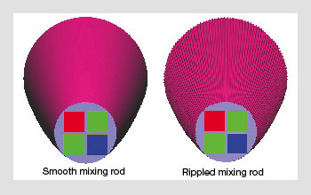 Smooth versus rippled mixing rods for color mixing LEDs. The taper provides an angle-to-area transformation, changing the full hemisphere Lambertian output of the LEDs into a distribution that fills a smaller cone angle (30 degree half cone angle in this example).
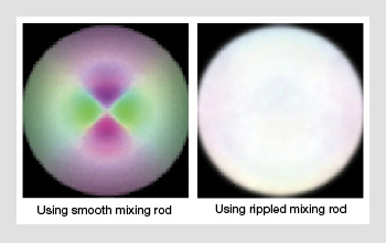
Illuminance at the mixer output. Raster plots show the illuminance at the output face of the mixer.
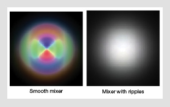
Angular distribution exiting the mixer. The image on the left shows the output of the smooth mixer. The image on the right shows the output from the mixer with ripples with a low angle diffuser applied to the output face.
Solid-state lighting
Solid-state lighting is a high growth area for high-brightness LEDs. It consists of semiconductors that convert electricity into light and commonly includes high-brightness LEDs as well as organic light-emitting diodes and light-emitting polymers. Solid-state lighting products are starting to emerge that will eventually displace conventional light source technologies.
In some cases, high-brightness LEDs are used with conventional optical technologies to provide beam patterns like conventional lighting fixtures. The LED light fixtures are sometimes packaged to replace conventional lamps, such as MR16 lamps.
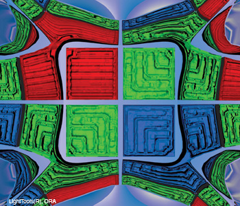
Unlike conventional lighting technologies, however, LED systems can allow color tunability by using groups of red, green and blue LEDs. With the proper balance of red, green and blue output, the color can be white; however, the color temperature can also be adjusted to match a user’s preference. Some systems even allow the color temperature to vary during the day, matching the color variation of the sun’s light.
However, most lighting fixtures require a constant color in the output distribution. Combining separate RGB LEDs to create a uniform white must be done carefully. One method for mixing the output from LEDs is to use mixing rods. The top figure on the right shows tapered smooth and rippled mixing rods. The taper provides an angle-to-area transformation, changing the full hemisphere Lambertian output of the LEDs into a distribution that fills a smaller cone angle (30 degree half cone angle in this example).
The mixer with ripples has the same macroscopic dimensions as the smooth mixer; however, fine structures primarily oriented along the length of the mixer are applied to the surface of the mixer. These ripples enhance the color mixing of the optical element, often providing a dramatic improvement in the color uniformity when used with RGB LEDs. The center figure shows a comparison between the luminance at the mixer output using a round smooth mixer and a round mixer with ripples.
The extents of the angular distribution exiting the smooth mixer and the mixer with ripples is similar. A lens can be used to reimage the output of the mixing rod, thereby creating a crisp circular spot pattern. Alternatively, a low angle diffuser can be applied to the output end of the mixing rod, which further enhances the angular color mixing and softens the edges of the angular distribution (see bottom figure).
Regulated illumination
In some applications, lighting output must meet legal or regulatory standards. Examples include automotive headlamps, automotive signal lamps and airport runway lights. LEDs are often used in these applications, especially in cases where the conventional technology uses a halogen lamp combined with a filter to produce the desired output color. LEDs do not need a filter; they can inherently produce the colors that match the regulated standards.
LED packages also have the benefit that the source emits light into a hemisphere rather than a sphere. The output pattern can be further reduced by adjusting the shape of the lens used in the LED package. This optical control can enable better optical designs, especially when the desired beam pattern has specific test points that must be satisfied.
Most automotive tail lamps have switched to LEDs. This was nominally driven by the conventional LED benefits of long life, high efficiency and insensitivity to vibrations. For automotive stop lamps, LEDs have the extra benefit of a faster turn-on time than conventional tungsten halogen lamps. This faster turn-on time provides an extra 60 feet of stopping distance at 60 mph.
Lighting the future
The growth in LED research and development has largely been driven by the high efficiency and long lifetime of this technology. However, LEDs offer many other benefits as well, including instant-on directionality for improved light utilization, mechanical robustness, dimmable color and low-voltage operation. They also do not require the addition of filters to remove radiated infrared and ultraviolet light and do not include toxic substances such as mercury. Although more work is needed to refine the technology, in the not-too-distant future we can expect LEDs to replace almost every light source we commonly use.
[ William J. Cassarly is with Optical Research Associates in Wooster, Ohio. ]
The renderings and simulations in this article were performed using LightTools(R) from Optical Research Associates.
References and Resources
>> R.V. Steele. “High-brightness LED market overview,” Proc. SPIE 4445, 1 (2001).
>> J. Petroski. “Thermal challenges facing new-generation light-emitting diodes (LEDs) for lighting applications,” Proc. SPIE 4776, 215-22 (2002).
>> Y. Ohno. “Color rendering and luminous efficacy of white LED spectra,” Proc. SPIE 5530, 88-98 (2004).
>> E. Hong and N. Narendran. “A method for projecting useful life of LED lighting systems,” Proc. SPIE 5187, 93-99 (2004).
>> Y. Narukawa. “White-Light LEDs,” Opt. Photon. News 15(4), 24-9 (2004).
>> J. Bisberg. “The 5 mm package versus the power LED: not a light choice for the luminaire designer,” LEDs Magazine, December 2005.
>> I. Ashdown. “Solid state lighting: a systems engineering approach,” Opt. Photon. News 18(1), 24-30 (2007).
>> J. Simmons et al. “Beyond the vacuum tube: lighting solutions for the 21st century,” Opt. Photon. News 18(6), 14-5 (2007).
>> W. Cassarly. “Backlight Pattern Optimization,” Proc. SPIE 6834, Paper 191, Nov. 2007.
>> M. Coltrin and J. Tsao. “Limits on the maximum attainable efficiency for solidstate lighting,” Proc. SPIE 6841, Paper 17, Nov. 2007.
>> LED info from Rennselaer Polytechnic Institute
>> Lamina Lighting