Optics’ origins are intimately linked with spherical surfaces. There are two reasons behind that surface-shape selection: First, spheres were the easiest surface to manufacture and polish precisely, and secondly, pre-computer-age optical design methods were based on algebra, for which spherical surfaces are a useful simplification, known as the paraxial, or Gaussian, approximation. Aspheric surfaces came later. Although the optical properties of some ideal rotational-symmetric aspheric surfaces were discovered centuries ago (parabolic and elliptical reflectors were known by the Greeks, and Descartes found their refractive counterparts in the 17th century), it was not until 1905 that Schwarzschild introduced the first designs with two interdependent aspheric surfaces. Eliminating the spheric constraint introduces degrees of freedom that can be used to improve system performance, reduce cost or both. The ability to design aspherics increased dramatically with the availability of computers, which allowed their optimization. However, the technology to manufacture them with optical accuracy remained limited throughout the 20th century. For years, aspherics remained difficult and expensive to manufacture and measure. The design and manufacture of imaging optics still relies mainly on spherical surfaces. Even when aspherics are used, manufacturers will allow only small departures from the best-fitting sphere. Modern manufacturing and measuring techniques will soon considerably relax this requirement, but optical design tools are less advanced and continue to limit extensive use of unrestricted asphericity.
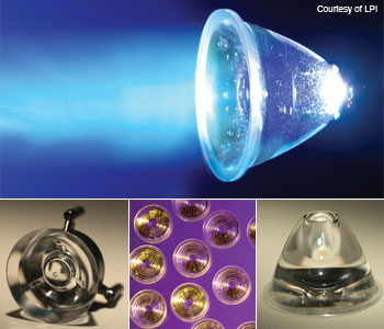
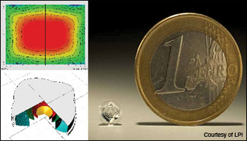
The field of nonimaging optics, which includes illumination optics, is a good arena for greater surface complexity. Its design techniques and goals are different from those of imaging optics, and its design methodology routinely uses radical aspherics. Also, manufacturing tolerances and performance goals are usually less demanding than for imaging optics. Therefore, both optical designers and manufacturers in this area have made extensive use of aspherics. For example, the images on the facing page show several popular collimators for LEDs, the design of which usually comprises highly aspheric surfaces manufactured by low-cost injection molding. The latest step that designers and engineers have taken to liberate themselves from restrictions on optical-surface geometry is to transcend rotational symmetry. Free-form surfaces (also called anamorphic surfaces, their formal name from Greek etymology) dramatically increase the degrees of design freedom. Many design problems with no theoretically perfect symmetrical-optics solution become tractable, and many times significantly improved, by discarding rotational symmetry. Most illumination-design problems with no symmetrical solution originate with the impossibility of achieving a 100 percent geometrical etendue coupling between the source and the target when their shapes have different symmetries (see the table for examples). Nevertheless, these problems are sometimes solvable when etendue coupling is significantly below 100 percent—the hallmark of inefficient systems. Nonimaging optics has pioneered free-form design and manufacturing. Free-form design techniques are much more advanced than those of imaging optics, generating simpler designs with better performance. Also, since nonimaging devices are generally more tolerant of surface errors than imaging ones, their mass production is easier. This is especially appealing because mass production has tight cost requirements; simpler designs are therefore highly beneficial. Both design and manufacturing of free-form surfaces require adequate mathematical equations to describe them. Although classical two-variable polynomials have been used, currently the most common representations are based on NURBS (non-uniform rational B-spline), which is widely used in CAD software packages. The future of optical design will be dominated by free-form surfaces, so we will now review free-form design methods in nonimaging optics, particularly for illumination, to understand current trends and challenges in progressing toward a complete free-form surface design methodology. These design methods are: multiparameter optimization, partial differential equations and the simultaneous multiple surface method. The last two methods directly generate a shape (the surfaces are “tailored”), whereas optimization is an iteration of successively improving design candidates. Free-form surface design by multiparameter optimizationIllumination design problems are usually defined by functionality. For example, the system must produce a prescribed intensity distribution. It is convenient to define a quantitative merit function Q that is to be minimized, and which also provides a metric for evaluating a solution. Multiparameter optimization design methods are based on analytic expressions for the free-form surfaces, expressions that depend on the particular parameters to be optimized. For example, consider a free-form reflector constrained to the N-order two-variable polynomial z = Σi+j≤N cijxiyj = c00+c10x+c01y+c20x2+c11xy+c02y2+...+c0NyN , with the coefficients cij being the parameters of interest. Since the merit function Q will depend on these parameters, this design method reduces to the mathematical problem of finding the global minimum of the function Q(cij). In most cases, the dependence of the merit function Q on parameters (cij) does not have a known analytic expression, so an iterative search must be made through the set of parameters’ values for the ones that minimize Q. The most common algorithms begin with an initial design and progress to the nearest minimum of the merit function. This local strategy cannot guarantee that the minimum is global. In fact, different techniques can be used to escape the local minima. For example, one can start from several distinct initial designs, use simulated annealing or use generic algorithms. |
The challenge in these optimizations is finding the global minimum as the number of parameters increases—for instance, when simultaneously optimizing two or more free-form surfaces when the polynomial order N is high. The complexity of that higher dimensionality greatly increases the number of local minima in Q, and thus greatly slows the algorithm. This is the main reason why only a few terms of the polynomial expansion are considered, so that typically the surface is restricted to be a low-order polynomial. In fact, optimizations customarily introduce their parameters successively: Low-order terms are added first, followed by higher-order ones. The initial design is just a guess by the optical designer, usually a simple surface such as a flat, a sphere, or a rotationally symmetric conic, or else a previous design. Usually the global minimum of Q is inaccessible and one rarely knows if it has been found! Sufficient designs are many times found with this design technique, although it is clearly not optimal. Free forms and partial differential equationsThe use of partial differential equations (PDEs) in optical design is rare. In imaging optics, PDEs have been used to design progressive lenses. In nonimaging optics, there are several examples: the Poisson Bracket method, which leads to first-order systems of PDEs that have a solution for a space-varying refractive index distribution of ideal concentrators in 3D; the Monge-Ampere type PDEs (nonlinear and second-order), which can solve problems with a point source and one free-form surface to produce prescribed irradiance; and two free-form surfaces, with prescribed irradiance and phase.
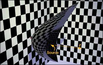
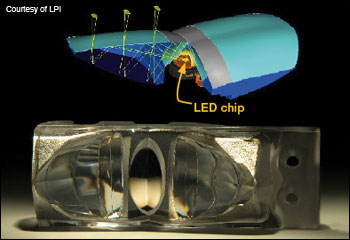
The middle figure on the right shows an example of a single free-form reflector designed to produce a rectangular intensity pattern (i.e., when the target is at infinity) for a point source that emits with an equatorial intensity pattern around a z axis. This pattern approximates that of on-axis filament lamps, for which the socket and a shield prevent axial emission. The point-source approximation becomes better as the mirror moves farther away from the light source. Because the point source approximation is present in all Monge-Ampere type problems, the reflectors (or lenses) designed using this method have an aperture that is much bigger than the etendue-minimum. The design procedure can be easily extended to other types of sources, provided they are formed by a single normal congruence of rays. So far, however, it cannot efficiently handle extended sources. A normal congruence of rays is defined as a set of rays with a family of wavefronts, or surfaces normal to its ray trajectories. The rays that are orthogonally associated with a spherical wavefront are a particular case of a normal congruence, which is sometimes called a point source. The simultaneous multiple surface (SMS) design methodThe development of the SMS method began after 1990, for the design of 2D profiles of non-imaging optical devices (SMS2D). It was a breakthrough in a field dominated by bulky designs. It produced a wide variety of ultra-compact rotationally symmetric devices performing very close to the theoretical limits (maximum concentration of radiation, minimum collimation angles, with 100 percent ray-transfer efficiency). Later advances in this SMS non-imaging method generated free-form optical surfaces in 3D (SMS3D), a major extension of SMS2D. As the only design tool capable of producing practical designs for extended sources in 3D, SMS3D represented a breakthrough in non-imaging optical designs. This method enables much better control of the light emitted by an extended light source than any free-form surfaces for a point source. In addition, it also allows the optical contour to be shaped without efficiency losses. For these reasons, the SMS3D method has already generated numerous illumination optics designs. Within the framework of geometrical optics, a single reflecting surface can transform a spherical wave into a plane wave. This surface is the parabolic reflector, a member of the class of curves known as Cartesian ovals. These surfaces, named after their discoverer Descartes (1596-1650), transform any spherical wave into any other one (one particular case is the plane wave) by reflection or by refraction. More than a century ago, Levi-Civita (1873-1941) generalized this concept, proving that a single deflecting surface (refractive or reflective) is enough to transform any normal congruence of rays into another normal congruence of rays. Once the input and output normal congruences are prescribed, there is a one-parametric family of deflecting surfaces that can transform one set into the other. Selecting one particular deflecting surface requires only a single parameter to be specified. For instance, we can give some point of the deflecting surface a definite spatial position. As a step further in this direction, SMS3D has proved that, in general, two surfaces are enough to transform two normal congruencies into another two. This method generates an optical system comprising at least two free-form surfaces that deflect (by refraction or by reflection) the rays of the input congruencies into the rays of the corresponding output congruencies, and vice versa. Unlike the case of Cartesian ovals and Levi-Civita’s surfaces, initial conditions not only include a point on one of the surfaces but a curve to be contained in one. This degree of freedom can impose additional ray-coupling conditions, which in practice lead to the ability to transform approximately a third input normal congruence into a corresponding output congruence. The bottom figure on the right shows as an example an RXI-based automotive luminaire, for a Lumileds Luxeon white LED. The RXI is a single optic formed by the two surfaces generated by the SMS3D design procedure: Light from the chip hits the upper surface, which totally internally reflects it back down toward the rear surface (except for a small central region using a reflective coating to do the same). The rear surface has a reflective coating that deflects it back toward the front surface, which refracts into its final exit direction as part of a well-formed beam. This optical folding gives the RXI both high-collection efficiency and great compactness. |
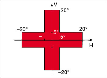
Considerably more development is needed for SMS methods, both at the theoretical and practical levels. These methods will be extended for more surfaces and more ray congruences. Such extensions are not trivial. One of the most exciting developments is imaging applications of SMS3D. The design procedure in 2D involves the simultaneous calculation of N axisymmetric surfaces, with the condition that N one-parameter ray bundles (and their symmetric counterparts) are perfectly imaged. The design strategy selects ray bundles that are evenly distributed in the phase space (i.e., the space-angle domain). By continuity, good image quality for those rays will guarantee sufficient image quality of all other rays through the system. This strategy was first used in the design of the RX, an ultra-high numerical aperture imaging device showing higher imaging quality than conventional aplanatic designs, for which the system is optimized only for first-order deviation from the on-axis point. Emerging illumination design modelsThese three methods for free-form surface designs—multiparameter optimization, partial differential equations and SMS—are very different. The question of which one works best depends on the specific problem. A good example of a challenging design problem was proposed at the 2006 International Optical Design Conference (IODC). This conference can be traced back to 1905, and has a long tradition of organizing interesting imaging lens design contests. For the 100th anniversary meeting, the conference included its first-ever contest on illumination design.
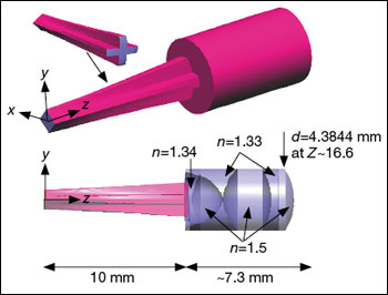
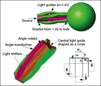
The two solutions that performed the best are shown on the right. The first-place winner, in the middle, was submitted by Bill Cassarly (ORA, USA). It was a square-to-cross converter comprising a solid free-form TIR light pipe (parameterized so the “speed” of conversion can be adjusted), coupled to a three-lens projection optic. The exit of the light pipe was optimized for a ±38º emission cone. The projection lens has the double function of focusing the 38º rays onto the rim of the exit lens (i.e., to make the exit lens rim coincide with the exit pupil in the imaging optics terminology) and to make the edge of the cross be projected toward 20 degrees. Despite the absorption in the materials (the system was over 17 mm long), the combination of graded interfaces made this improved projection lens reach a merit function of 0.750. The second-place winner was submitted by Julio Chaves (LPI-LLC, USA) and Dejan Grabovickic and Fernando Garcia (Universidad Politécnica de Madrid, Spain). Their design also had two stages: a square-to-cross converter and a projection lens. The projection lens was a spherically symmetric graded index lens, as designed by Morgan in 1958, with refractive index profile going from n=1.56 at the center to n=1.33 at the sphere’s edge. This Morgan lens collimates perfectly in 3D geometry and within the geometrical-optics approximation, with all rays emitted by a point source placed in air very close to its surface. (The Morgan lens is a generalization of the Luneburg lens.) This lens is therefore an ideal projection lens, to which the square-to-cross converter is to be coupled. The difference, however, between this projection lens and Cassarly’s is the input ray bundle it accepts, which is formed by all the rays hitting a virtual sphere of radius R/1.33, where R is the Morgan lens radius (this virtual sphere is the input pupil in the imaging terminology). The first stage makes the square-to-cross conversion by using light pipes that includes a combination of light shifters, angle transformers and angle rotators. Besides its sophistication, this system had a merit function of 0.706. Its main performance limitation resulted from the mis-coupling of the light pipes and the projection lens: The intensity out of the guides did not fully illuminate the previously mentioned virtual sphere. The winning solution used an optimizer integrated into the design. Therefore, it can be classified as a multiparameter optimization design. On the other hand, the second-place approach used the nonimaging optics edge-ray theorem, but not numerically optimized. This underscored the importance of optimization methods—which, if they had been applied to the design, could have improved its mis-coupling problem. At the same time, however, the optimization procedures themselves do not yet provide good solutions. (Other multiparameter optimization designs were submitted, with poorer performance). Thus, the designer’s insight into the proper initial configuration and its parameterization is crucial. The future of illumination design will likely be dominated by a combination of direct methods such as the SMS or PDE to provide a starting point for a design, with optimization methods used for the fine tuning. Pablo Benítez and Juan C. Miñano are with the Universidad Politécnica de Madrid, Cedint, ETSI Telecomunicación, C. Universitaria, in Madrid, Spain, and Light Prescriptions Innovators LLC, in Altadena, Calif.
References and Resources |