

Within minutes of landing, the twin Mars Exploration Rovers brought home the crowning success of the moment by transmitting spectacular images to Earth. Years of advances in deep space communication and navigation contributed to this feat, which established a virtual tele-presence on Mars. This communications capacity will no doubt extend throughout the solar system and beyond with further advancement in deep-space technologies.
However, before that can happen, we must develop better communications tools. Specifically, deep-space science and exploration will rapidly encounter a bandwidth ceiling with radio frequencies of S-, X- and Ka-bands. In addition, communicating at a given data-rate with an outer planet such as Neptune or Pluto is 1,000 times more difficult than communicating at nominal Mars distance, and approximately 10 billion times more challenging than communicating from geosynchronous orbit (GEO) to the ground. On space platforms, mass and electrical power are expensive commodities, and thermal gradients and ionizing radiation pose challenges as well.
Using conventional planetary spacecraft telecommunications technology, the latest spacecraft is limited over its mission lifetime to mapping less than two percent of the surface of the planet Mars, due to the data downlink to Earth. With the use of space-based, free-space laser communications (lasercom), however, Mars could be mapped at a rate of more than 100 times what is possible with the current implementation strategy.
The high-capacity communications offered by lasercom could enable scientists to communicate information from other planets using, for example, streaming HDTV video, synthetic aperture radar, multi- and hyper-spectral imagers, precision navigation and multi-channel telecommunications. Also possible are multi-functionality with space-based optical navigations, laser remote sensing, imaging and altimetery.
Lasercom could offer these benefits with no additional attitude control burden on the spacecraft, and no spectrum bandwidth allocation or restrictive frequency regulations. With comparable mass and power of a radio-frequency communication system, including optics that are one-tenth the diameter of the flight antenna aperture, lasercom systems are expected to deliver at least an order-of-magnitude higher data rate.
Lasercom is being considered as a way to meet the planetary distance telecommunications requirements at multi-hundreds of megabits to gigabits per second data rates projected for 2020 and beyond. Over the past decade, near-Earth laser communications were successfully demonstrated in space from low-Earth-orbit (LEO), LEO-to-GEO, and as high as 10 Gb/s from GEO.
These in-space validations of the technology have led to the development of operational systems. Although lasercom has been fairly well proven in Earth’s orbit, it will need to undergo a number of successful deep-space demonstrations—with an order-of-magnitude higher data rate and at a lower cost per bit than conventional systems—before it can be operationally implemented in space. To date, there have been no laser telecommunications with a planetary spacecraft, although there have been demonstrations of aiming a ground-based laser at spacecraft into deep space and vice versa.
In 2004, NASA established the Mars Laser Communication Demonstration (MLCD) project to demonstrate the first deep space optical link. Lincoln Laboratory, NASA-JPL and NASA-Goddard were partners in this effort.
Although the project was subsequently canceled, it provided opportunities to improve lasercom technology. A formal review of MLCD’s design showed that deep-space lasercom technology has matured enough for in-space validation. There remains an enormous potential for improving link performance through technological advancement.
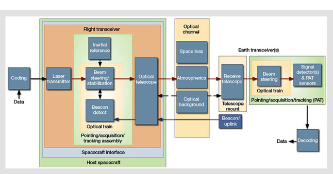
A top-level optical communications signal flow is depicted in the figure below. Degraded performance in any of the subsystem blocks, or a capabilities mismatch among various blocks, will result in reduced efficiency of data transmission. The behavior of the flight transceiver can be influenced by a number of factors, including the space environment (radiation and vacuum), the host spacecraft random vibrations, and the interface between the space platform and the transceiver. Transmitting a laser beam through Earth’s turbid and turbulent atmosphere are the next major hurdles.
Signal detection
Non-coherent (direct) detection and coherent detection are two primary signal-receiving options for lasercom. The theoretical limit for photon-counting direct detection is 36.2 bits/photon (at 1,064 nm and 270 K). JPL has operated 60 megabits/s (Mb/s) in end-to-end laboratory Mars link emulations at validated link efficiencies of 2 to 2.5 bits per detected photon. This is better than the theoretical coherent heterodyne limit of 1.44 bits/photon, and approaches the coherent homodyne limit of 2.87 bits/photon. Receivers for a data rate of 1.6 Gb/s are now under development.
Navigation and precision ranging data are also provided by the spacecraft’s telecommunications subsystem. Doppler information is gleaned from the recovered pulse-position-modulation (PPM) slot clock. With precision on the order of 3 mm, spacecraft range data can be inferred from coding frame boundaries. Analysis and simulations indicate that, depending on how the PPM slot clock is phase-locked, Doppler and range data two to ten-times better than Ka-band can be obtained using PPM and direct detection.
|
Communications signal flow between a spacecraft probe and Earth. |
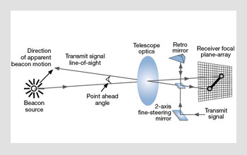
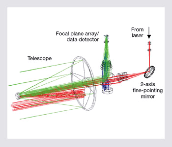 Transceiver optical train. The system consists of a common transmit/receive aperture and a minimum of three optical paths: transmit, receive and boresight. The transmit laser signal bounces off of a two-axis fine pointing mirror before traveling out through the telescope. The beacon signal from a remote optical receiver is imaged onto a detector array for spatial acquisition and tracking. The receive path may be used to uplink data reception or beacon signal reception to aid with acquisition, tracking and precision beam pointing. A small portion of the transmit signal is also imaged onto the focal plane.
Photon-counting detectors
Deep-space lasercom links operate in the photon-starved regime, in that the portion of laser-transmitted laser power received at the other end of the link is significantly diminished with range. Efficient detection of PPM signals at high data rates set two key requirements on the photodetector: high photon detection efficiency (0.5-0.9) and output pulse jitter approaching tens of picoseconds. Single photon-sensitive photodetectors with enormously high gain and extremely low noise can result in an 8- to 10-dB improvement in the link performance.
State-of-the-art photodetectors are advancing at a rapid pace. Devices that simultaneously satisfy all desirable characteristics—such as high detection efficiency, low noise, low jitter and no reset circuitry—are expected to become available in the next two years. Promising devices under development include Si or InGaAs negative avalanche feedback photodiodes; Si or InGaAs photodetectors with internal discrete amplification; superconducting niobium photodetectors; Geiger-mode InGaAsP/InP avalanche photodetectors; and InGaAsP intensified photo-
detectors.
Modulation and coding
Today’s efficient codes can achieve performance to within less than 1 dB of capacity. Sub-nanosecond slot widths are required for efficient modulation at high order PPM implementation. Researchers at JPL have recently developed encoders and modulators that operate at slot rates down to 0.1 ns with real-time data inputs to 1.6 Gb/s.
Slot widths down to 0.025 ns can be achieved by multiplexing multiple PPM encoders using off-the-shelf fiber-optic multiplexers. The encoder output feeds into a well-behaved, low-power laser (oscillator) in a master oscillator power amplifier configuration.
Flight laser transmitter
The required laser output power is driven by the desired data rate at a given link distance and the modulation format. High-order PPM provides the most efficient link for deep-space laser links. PPM implementation necessitates high peak-to-average output power lasers. Pulsed fiber-amplifiers that use Yb-doped (1,060 nm) or Er/Yb-doped (1,550 nm) fiber provide adequate average and peak (instantaneous) power levels to satisfy link requirements. The 1,550-nm sources are preferred due to the availability of Telcordia-qualified components. However, 1,060-nm lasers offer superior wall-plug efficiency by as much as a factor of two, compared to current 1,550-nm lasers.
An overall oscillator/amplifier efficiency of 30 percent is theoretically achievable. Current transmitter efficiency stands at approximately 15 percent. Pulsed fiber amplifiers with 10-W average power and near 1 kW peak power are now commercially available. Self phase modulation currently limits the laser pulse-widths to approximately 50 ps.
Pointing and stabilizing
The high (optical) antenna gain, resulting from low beam divergence of optical beams, gives lasercom its significant advantage over conventional communication systems. However, with this benefit comes the challenge of having to point the laser beam with sub-micro-radian (µrad) accuracy to a target tens to hundreds of millions of kilometers away.
A lasercom transceiver can use coarse pointing (approximately 0.1 degree), typically provided by the spacecraft probe to the planetary radio frequency communications systems, to acquire the Earth-based receiver within its acquisition field of view. Fine beam pointing and point-ahead/behind is accomplished by way of internal mechanisms within the lasercom transceiver.
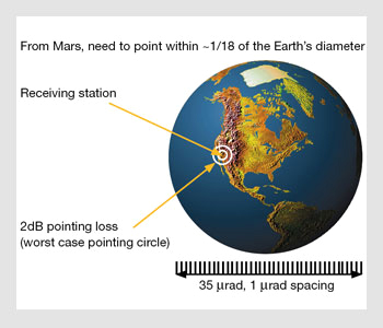 Transmit beam pointing requirements. The static error allocation is shown as the inner circle around the Earth. The 2-dB allocation (the outer circle) is the maximum footprint diameter for the beam arriving from Mars without further degrading the link performance.
Inaccurate laser beam pointing will result in a severely degraded link margin and system performance due to large signal fades at the receiver. The 3-sigma total pointing accuracy is defined as 3x jitter + bias. The angular width of a 1,000-nm laser beam transmitted through a 30-cm diameter telescope is approximately 3.3 µrad. Because of statistical pointing-induced fades (PIF) and mis-point angles, a pointing loss is typically allocated to the power link margin. For example, a 2-dB pointing loss allocation with a 1 percent PIF requires a total (3-sigma) pointing accuracy of 2 µrad.
This pointing loss allocation is then divided into bias and jitter mis-point errors. These losses may be mitigated by introducing an interleaver that spreads a PIF over many code-words of an error correction code. To effectively deliver the signal to the ground station, the lasercom transmitter must be capable of tracking the receiving station such that the tracking jitter error is less than approximately 10 percent of the transmit beam-width (roughly 0.33 µrad). From Mars, Earth extends about 35 µrad.
Therefore, with a flight transmit aperture of 30 cm, and at the nominal Earth-Mars distance, the 1,000-nm transmit laser beam needs to be pointed to approximately 1/18th of the Earth’s diameter, shown as the inner circle on the figure on the right. This pointing requirement is orders-of-magnitude more precise than the radio frequency system requirement.
The requirement for sub-µrad pointing is further compounded by the undesirable host spacecraft platform’s angular micro-vibrations stemming from guidance and control activities, such as momentum dumping and retro-rocket firings. The extent of these micro-vibrations frequencies spans from less than 0.1 Hz to hundreds of Hz. Also, their amplitude is typically much larger than the transmit beam width. High frequencies (greater than several hundred Hz) may be rejected, for example, via passive isolators and/or inertially referenced stabilized platforms.
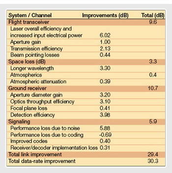 Link improvements needed for 30-dB enhancement in data rate.
Rejection of lower frequencies requires assistance from a reliable beacon signal and a dedicated pointing control subsystem to maintain accurate beam pointing. Examples of a suitable beacon include: laser emanated from Earth, a sun-illuminated Earth imaged in the visible or infrared region of the spectrum, and precision star tracking.
The total pointing error for a lasercom transceiver is mainly composed of the errors in position determination, inaccuracies in boresight calibration (not detectable by the tracking detector) and residual tracking errors not compensated for by the pointing subsystem control loop. The residual tracking error results from inadequate compensation of the host platform vibrations by the pointing control loop.
In general, the higher the bandwidth of the control loop, the better the platform jitter compensation, and therefore the lower the residual pointing error. Without assistance from an inertial navigation subsystem that is joined intimately with the transceiver for tracking a ground-based receiver site from space, the system may require image centroiding update rates as high as several kHz.
Flight telescope and optical channel
A highly stable opto-mechanical and thermo-mechanical assembly is critical in order to meet the sub-µrad laser pointing accuracy requirement. Even though transmit receive signal isolation is more of a challenge, optical systems that combine both the transmitter and the (beacon and signal) receive aperture in one assembly are less susceptible to drift between channels.
A solar background light-rejecting window at the telescope will minimize heat load from sunlight entering the telescope, while an optical system class with cleanliness of 300 or better diminishes the scattered light that can find its way to any one of the sensors in the system.
Atmospheric attenuation and turbulence can result in signal fades, beam spreading at the telescope focal plane, wavefront tip/tilt, background light due to sky radiance and other undesirable phenomena. The effect is more pronounced on the uplink beam than the downlink. When one is using multi-meter-diameter ground telescopes for reception of downlink signals, the aperture-averaging effect and multi- (4- to 16-) beam uplink can both mitigate some of the atmospheric turbulence effects on the beam. A significant portion of the atmospheric-induced optical link degradation can be allayed through proper site selection.
Ground-based telescopes
To communicate efficiently with deep space, ground-based optical receiver telescopes must have aperture diameters at least in the range of 5-10 m. Alternatively, an array of smaller diameters (about 2 m), each equipped with a very low noise photon counting detector, can constitute an effective large aperture as well.
Since the objective is photon collection (as opposed to imaging), the telescopes do not have to be of diffraction-limited quality, though overall optical surface smoothness is important. Overall wavefront quality of about 1 wave at 1,060 nm may be adequate.
The telescope should be able to operate during night and day, at times to within less than 3 degrees of the sun. Narrow-band optical filtering at the opto-electronic receiver should have wide enough spectral width to account for laser transmitter beam width, detection jitter and Doppler shift of the transmit laser wavelength. A tunable filter will assist the latter effect.
We are now experimenting with approaches to develop low-cost 2-m-diameter class receiving stations suitable for planetary laser-communications. For example, we developed a method for correcting slowly varying wavefront aberrations of low-quality telescope mirrors, using a deformable mirror in an active optical compensation system. Our goal was to reduce the surface wavefront error of low-cost multi-meter-diameter mirrors from about 10 waves peak-to-valley (P-V) at 1 µm wavelength, to approximately 1 wave or less.
 Spatial tracking with a single focal plane array detector. A schematic representation of a concept for tracking the sun-illuminated Earth image or a laser beam emanated from the Earth receiver site with a pixilated imager at the focal plane of the flight optical system.
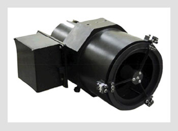 Laser-communications transceiver. Optical assembly of a 10-cm-aperture diameter flight transmitter developed based on the focal-plane-array tracking concept.
Future directions
Ongoing optical technology advances should allow 30 dB of increased data rates relative to MLCD by 2020. In other words, we could expect the return of deep space data at rates of 1Gb/s from the maximum Mars range, 100 Mb/s from Jupiter distances and 10 Mb/s from Uranus.
Technology at the component, subsystem and system levels has advanced enough to successfully validate the lasercom technology at the maximum Mars range with data-rates approaching 100 Mb/s—more than an order of magnitude beyond the state-of-the-art radio frequency communications systems. There is opportunity for an additional 30 dB of link margin improvement.
When realized, the additional link margin may be used to increase the data rate while reducing mass, size and complexity of the flight transceiver. Data rates on the order of 1 Gbits/s from Mars will be within reach in the next couple of decades, enabling significant data return and streaming high quality video from other planets to Earth. However, the light science enabled by lasercom (akin to radio science) remains a largely unexplored field.
Some of the remaining engineering challenges include circumventing attenuation due to atmosphere, achieving communications within a few degrees of the sun-angle, and addressing the inadequacy of ground station infrastructure. While future Earth-based optical receivers may be located on airborne or Earth-orbiting platforms to circumvent atmospheric issues, technology and operational demonstrations for the first decade or so of deep-space laser communications will likely rely on lower risk and less expensive ground-based receivers.
Ground station diversity can adequately mitigate cloud cover. Large diameter membrane filters located at the entrance aperture of ground-based telescopes will aid with communications at small sun angles. The advent of affordable, large diameter, non-diffraction-limited ground telescopes should make infrastructure development realizable.
The work described here was performed at the Jet Propulsion Laboratory (JPL), California Institute of Technology under contract with the National Aeronautics and Space Administration (NASA).
[Hamid Hemmati is with the Jet Propulsion Laboratory (JPL), California Institute of Technology, Pasadena, Calif.]
References and Resources
>> L. Robinson and T. Meink. “Transformational Communications,” AFRL Technology Horizons, pp.10-11 (June 2005).
>> R.J. Barron and D.M. Boroson. “Analysis of Capacity and Probability of Outage for Free-Space Optical Channels with Fading due to Pointing and Tracking Error,” Proc. SPIE, G.S. Mecherle, ed., 6105 (March 2006).
>> H. Hemmati and Y. Chen. “Active optical compensation of low-quality optical system aberrations,” Opt. Lett. 31, 1630-2 (2006).
>> H. Hammati, ed. “Deep Space Optical Communications,” Wiley (2006).
>> W.D. Williams et al. “RF and Optical Communications: A Comparison of High Data Rate Returns from Deep Space in the 2020 Timeframe,” Proceedings of the 12th Ka and Broadband Communications Conference, Naples, Italy (September 2006), Paper K000083.
>> M.K. Cheng et al. “Implementation of a Coded Modulation for Deep Space Optical Communications,”Global Telecommunications Conference, 2006. GLOBECOM ‘06. IEEE, pp. 1-5 (Nov. 2006).
>> H. Hemmati et al. “Prospects for Improvement of Interplanetary Laser-Communication Data-Rates by 30 dB,” Proc. IEEE (Fall 2007).
>> K. Zhao et al. “InGaAs single photon avalanche detector with ultra low excess noise,“ to be published in Appl. Phys. Lett. 91, 081107 (2007).